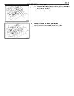
6.
INSPECT CYLINDER HEADS FOR FLATNESS
Using precision straight edge and feeler gauge, measure
the surfaces contacting the cylinder block and manifolds
for warpage.
Maximum warpage: 0.10 mm (0.0039 in.)
If warpage is greater than maximum, replace the cylinder
head.
7.
INSPECT CYLINDER HEAD FOR CRACKS
Using a dye penetrant, check the combustion chamber, in-
take ports, exhaust ports and cylinder block surface for
cracks.
If cracked, replace the cylinder head.
8. CLEAN
VALVES
(a) Using a gasket scraper, chip off any carbon from the
valve head.
(b) Using a wire brush, thoroughly clean the valve.
9.
INSPECT VALVE STEMS AND GUIDE BUSHINGS
(a) Using a caliper gauge, measure the inside diameter of
the guide bushing.
Bushing inside diameter:
6.010–6.030 mm (0.2366–0.2374 in.)
EM-40
ENGINE MECHANICAL – Cylinder Heads
Summary of Contents for 2VZ-FE
Page 1: ...ENGINE MECHANICAL EM 1 ENGINE MECHANICAL Description Operation ...
Page 31: ...CYLINDER HEADS COMPONENTS EM 29 ENGINE MECHANICAL Cylinder Heads ...
Page 63: ...CYLINDER BLOCK REMOVAL OF ENGINE EM 61 ENGINE MECHANICAL Cylinder Block ...
Page 64: ...EM 62 ENGINE MECHANICAL Cylinder Block ...
Page 71: ...COMPONENTS EM 69 ENGINE MECHANICAL Cylinder Block ...
Page 106: ...EFI SYSTEM FI 1 ...
Page 107: ...DESCRIPTION FI 2 EFI SYSTEM Description ...
Page 111: ...OPERATION System Circuit FI 4 EFI SYSTEM Operation System Circuit ...
Page 121: ...FUEL SYSTEM Fuel Pump EFI SYSTEM Fuel System Fuel Pump FI 15 ...
Page 141: ...Fuel Tank and Lines COMPONENTS EFI SYSTEM Fuel System Fuel Tank and Lines FI 35 ...
Page 172: ...EXHAUST SYSTEM EXHAUST SYSTEM REPAIR INSTRUCTIONS EX 1 ...
Page 174: ...EMISSION CONTROL SYSTEMS EC 1 ...
Page 186: ...COOLING SYSTEM CO 1 ...
Page 205: ...LUBRICATION SYSTEM LUBRICATION SYSTEM Description Operation LU 1 ...
Page 224: ...IGNITION SYSTEM IG 1 ...
Page 237: ...SERVICE SPECIFICATIONS IG 14 IGNITION SYSTEM ServiceSpecifications ...
Page 238: ...ENGINE TROUBLESHOOTING TR 1 ...


