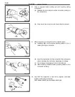
8. Care is required when pulling out and inserting wiring
connectors.
(a) Release the lock and pull out the connector, pulling on
the connectors.
(b) Fully insert the connector and check that it is locked.
9.
When inspecting a connector with a volt/ohmmeter.
(a) Carefully take out the water–proofing rubber if it is a
water–proof type connector.
(b) Insert the test probe into the connector from wiring side
when checking the continuity, amperage or voltage.
(c) Do not apply unnecessary force to the terminal.
(d) After checking, install the water–proofing rubber on the
connector securely.
10. Use SST for inspection or test of the injector, cold start
injector or its wiring connector.
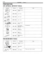
SST 09842–30050 (A) and 09842–30070 (B)
FI–12
–
EFI SYSTEM
Inspection Precautions
Summary of Contents for 2VZ-FE
Page 1: ...ENGINE MECHANICAL EM 1 ENGINE MECHANICAL Description Operation ...
Page 31: ...CYLINDER HEADS COMPONENTS EM 29 ENGINE MECHANICAL Cylinder Heads ...
Page 63: ...CYLINDER BLOCK REMOVAL OF ENGINE EM 61 ENGINE MECHANICAL Cylinder Block ...
Page 64: ...EM 62 ENGINE MECHANICAL Cylinder Block ...
Page 71: ...COMPONENTS EM 69 ENGINE MECHANICAL Cylinder Block ...
Page 106: ...EFI SYSTEM FI 1 ...
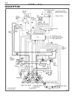
Page 107: ...DESCRIPTION FI 2 EFI SYSTEM Description ...
Page 111: ...OPERATION System Circuit FI 4 EFI SYSTEM Operation System Circuit ...
Page 121: ...FUEL SYSTEM Fuel Pump EFI SYSTEM Fuel System Fuel Pump FI 15 ...
Page 141: ...Fuel Tank and Lines COMPONENTS EFI SYSTEM Fuel System Fuel Tank and Lines FI 35 ...
Page 172: ...EXHAUST SYSTEM EXHAUST SYSTEM REPAIR INSTRUCTIONS EX 1 ...
Page 174: ...EMISSION CONTROL SYSTEMS EC 1 ...
Page 186: ...COOLING SYSTEM CO 1 ...
Page 205: ...LUBRICATION SYSTEM LUBRICATION SYSTEM Description Operation LU 1 ...
Page 224: ...IGNITION SYSTEM IG 1 ...
Page 237: ...SERVICE SPECIFICATIONS IG 14 IGNITION SYSTEM ServiceSpecifications ...
Page 238: ...ENGINE TROUBLESHOOTING TR 1 ...


