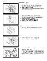
19. INSTALL RH ENGINE MOUNTING INSULATOR
(a) Attach the mounting insulator to the mounting bracket
and body, temporarily install the mounting insulator four
nuts, bolt the mounting stay bolt (A).
(b) Torque the mounting insulator with four nuts and bolt.
Do not torque the mounting stay bolt (A) yet.
Torque:
Bolt
650 kg–cm (47 ft–lb, 64 N
⋅
m)
Nut
To bracket
530 kg–cm (38 ft–lb, 52 N
⋅
m)
To body
900 kg–cm (65 ft–lb, 88 N
⋅
m)
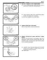
(c) Install the two clamp bolts of the PS oil cooler pipes.
20. LOWER
ENGINE
21. INSTALL RH ENGINE MOUNTING STAYS
(a) Install the No.1 mounting stay with the three bolts.
Torque the bolts.
Torque: 530 kg–cm (38 ft–lb, 52 N
⋅
m)
(b) Install the No.2 mounting stay with the bolt and nut.
Torque the bolt and nut.
Torque:
Bolt 670 kg–cm (48 ft–lb, 66 N
⋅
m)
Nut 530 kg–cm (38 ft–lb, 52 N
⋅
m)
22. INSTALL PS PUMP DRIVE BELT
Adjust the drive belt.
Drive belt tension: New belt 125
±
20 lb
Used belt 80
±
25 lb
23. INSTALL ALTERNATOR DRIVE BELT
Adjust the drive belt. (See pages
)
Drive belt tension: New belt 175
±
5 lb
Used belt 115
±
20 lb
24. INSTALL RH FRONT FENDER APRON SEAL
25. INSTALL RH FRONT WHEEL
26. INSTALL PS OIL RESERVOIR TANK
(See step 6 on page
27. INSTALL CRUISE CONTROL ACTUATOR
(See step 27 on page
)
28. INSTALL SUSPENSION UPPER BRACE
(See step 35 on page
)
29. CONNECT CABLE TO NEGATIVE TERMINAL OF
BATTERY
EM-28
ENGINE MECHANICAL – Timing Belt
Summary of Contents for 2VZ-FE
Page 1: ...ENGINE MECHANICAL EM 1 ENGINE MECHANICAL Description Operation ...
Page 31: ...CYLINDER HEADS COMPONENTS EM 29 ENGINE MECHANICAL Cylinder Heads ...
Page 63: ...CYLINDER BLOCK REMOVAL OF ENGINE EM 61 ENGINE MECHANICAL Cylinder Block ...
Page 64: ...EM 62 ENGINE MECHANICAL Cylinder Block ...
Page 71: ...COMPONENTS EM 69 ENGINE MECHANICAL Cylinder Block ...
Page 106: ...EFI SYSTEM FI 1 ...
Page 107: ...DESCRIPTION FI 2 EFI SYSTEM Description ...
Page 111: ...OPERATION System Circuit FI 4 EFI SYSTEM Operation System Circuit ...
Page 121: ...FUEL SYSTEM Fuel Pump EFI SYSTEM Fuel System Fuel Pump FI 15 ...
Page 141: ...Fuel Tank and Lines COMPONENTS EFI SYSTEM Fuel System Fuel Tank and Lines FI 35 ...
Page 172: ...EXHAUST SYSTEM EXHAUST SYSTEM REPAIR INSTRUCTIONS EX 1 ...
Page 174: ...EMISSION CONTROL SYSTEMS EC 1 ...
Page 186: ...COOLING SYSTEM CO 1 ...
Page 205: ...LUBRICATION SYSTEM LUBRICATION SYSTEM Description Operation LU 1 ...
Page 224: ...IGNITION SYSTEM IG 1 ...
Page 237: ...SERVICE SPECIFICATIONS IG 14 IGNITION SYSTEM ServiceSpecifications ...
Page 238: ...ENGINE TROUBLESHOOTING TR 1 ...


