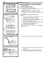
(e) Apply a light coat of engine oil on the threads and under
the heads of bearing cap bolts.
(f) Install and uniformly tighten the eight bearing cap bolts
in several passes in the sequence shown.
Torque: 160 kg–cm (12 ft–lb, 16 N
⋅
m)
(g) Remove the service bolt (B).
5.
CHECK AND ADJUST VALVE CLEARANCE
(See page
Turn the camshaft and position the cam lobe upward, and
check and adjust the valve clearance.
Valve clearance (Cold):
Intake
0.13–0.23 mm (0.005–0.009 in.)
Exhaust
0.27–0.37 mm (0.011–0.015 in.)
6.
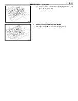
INSTALL CAMSHAFT OIL SEALS
(a) Apply MP grease to a new oil seal lip.
(b) Using SST, tap in the oil seals.
SST 09223–46011
7.
INSTALL SPARK PLUG TUBE GASKETS
Install the six tube gaskets.
EM-55
ENGINE MECHANICAL – Cylinder Heads
Summary of Contents for 2VZ-FE
Page 1: ...ENGINE MECHANICAL EM 1 ENGINE MECHANICAL Description Operation ...
Page 31: ...CYLINDER HEADS COMPONENTS EM 29 ENGINE MECHANICAL Cylinder Heads ...
Page 63: ...CYLINDER BLOCK REMOVAL OF ENGINE EM 61 ENGINE MECHANICAL Cylinder Block ...
Page 64: ...EM 62 ENGINE MECHANICAL Cylinder Block ...
Page 71: ...COMPONENTS EM 69 ENGINE MECHANICAL Cylinder Block ...
Page 106: ...EFI SYSTEM FI 1 ...
Page 107: ...DESCRIPTION FI 2 EFI SYSTEM Description ...
Page 111: ...OPERATION System Circuit FI 4 EFI SYSTEM Operation System Circuit ...
Page 121: ...FUEL SYSTEM Fuel Pump EFI SYSTEM Fuel System Fuel Pump FI 15 ...
Page 141: ...Fuel Tank and Lines COMPONENTS EFI SYSTEM Fuel System Fuel Tank and Lines FI 35 ...
Page 172: ...EXHAUST SYSTEM EXHAUST SYSTEM REPAIR INSTRUCTIONS EX 1 ...
Page 174: ...EMISSION CONTROL SYSTEMS EC 1 ...
Page 186: ...COOLING SYSTEM CO 1 ...
Page 205: ...LUBRICATION SYSTEM LUBRICATION SYSTEM Description Operation LU 1 ...
Page 224: ...IGNITION SYSTEM IG 1 ...
Page 237: ...SERVICE SPECIFICATIONS IG 14 IGNITION SYSTEM ServiceSpecifications ...
Page 238: ...ENGINE TROUBLESHOOTING TR 1 ...


