RADIATOR
CLEANING OF RADIATOR
Using water or a steam cleaner, remove any mud and dirt
from the radiator core.
NOTICE: If using a high pressure type cleaner, be careful
not to deform the fins of the radiator core. If the cleaner
nozzle pressure is 30–35 kg/cm
2
(427–498 psi, 2,942–3,432
kPa), keep a distance at least 40–50 cm (15.75–19.69 in.)
between the radiator core and cleaner nozzle.
INSPECTION OF RADIATOR
1. INSPECT
RADIATOR
CAP
NOTICE: When performing steps (a) and (b) below, keep
the radiator pump tester at an angle of approx. 30
°
above
the horizontal.
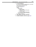
(a) Using a radiator cap tester, slowly pump the tester and
check that air is coming from the relief valve.
Pump speed: 1 push/3 seconds or more
NOTICE: Push the pump at a constant speed.
If air is not coming from the relief valve, replace the radiator
cap.
(b) Pump the tester several times and measure the relief
valve opening pressure.
Pump speed:
1st time
1 push/1 second or less
2nd time or more
Any speed
Standard opening pressure:
0.75–1.05 kg/cm
2
(10.7–14.9 psi, 74–103 kPa)
Minimum opening pressure:
0.6 kg/cm
2
(8.5 psi, 59 kPa)
If the opening pressure is less than minimum, replace the ra-
diator cap.
2.
INSPECT COOLING SYSTEM FOR LEAKS
(a) Fill the radiator with coolant and attach a radiator cap
tester.(b) Warm up the engine.
(c) Pump it to 1.2 kg/cm
2
(17.1 psi, 118 kPa), check that
pressure does not drop.
If the pressure drops, check for leaks as the hoses, radiator
or water pump. If no external leaks are found, check the heat-
er core, cylinder block and head.
–
COOLING SYSTEM
Radiator
CO–11
Summary of Contents for 2VZ-FE
Page 1: ...ENGINE MECHANICAL EM 1 ENGINE MECHANICAL Description Operation ...
Page 31: ...CYLINDER HEADS COMPONENTS EM 29 ENGINE MECHANICAL Cylinder Heads ...
Page 63: ...CYLINDER BLOCK REMOVAL OF ENGINE EM 61 ENGINE MECHANICAL Cylinder Block ...
Page 64: ...EM 62 ENGINE MECHANICAL Cylinder Block ...
Page 71: ...COMPONENTS EM 69 ENGINE MECHANICAL Cylinder Block ...
Page 106: ...EFI SYSTEM FI 1 ...
Page 107: ...DESCRIPTION FI 2 EFI SYSTEM Description ...
Page 111: ...OPERATION System Circuit FI 4 EFI SYSTEM Operation System Circuit ...
Page 121: ...FUEL SYSTEM Fuel Pump EFI SYSTEM Fuel System Fuel Pump FI 15 ...
Page 141: ...Fuel Tank and Lines COMPONENTS EFI SYSTEM Fuel System Fuel Tank and Lines FI 35 ...
Page 172: ...EXHAUST SYSTEM EXHAUST SYSTEM REPAIR INSTRUCTIONS EX 1 ...
Page 174: ...EMISSION CONTROL SYSTEMS EC 1 ...
Page 186: ...COOLING SYSTEM CO 1 ...
Page 205: ...LUBRICATION SYSTEM LUBRICATION SYSTEM Description Operation LU 1 ...
Page 224: ...IGNITION SYSTEM IG 1 ...
Page 237: ...SERVICE SPECIFICATIONS IG 14 IGNITION SYSTEM ServiceSpecifications ...
Page 238: ...ENGINE TROUBLESHOOTING TR 1 ...


