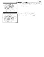
(c) Using a spring tester, measure the tension of the valve
spring at the specified installed length.
Installed tension:
18.6–21.4 kg (41.0–47.2 lb, 182–210 N)
at 33.8 mm (1.331 in.)
If the installed tension is not as specified, replace the valve
spring.
14. INSPECT CAMSHAFTS AND BEARINGS
A.
Inspect camshaft for runout
(a) Place the camshaft on V–blocks.
(b) Using a dial indicator, measure the circle runout at the
center journal.
Maximum circle runout: 0.06 mm (0.0024 in.)
If the circle runout is greater than maximum, replace the cam-
shaft.
B.
Inspect cam lobes
Using a micrometer, measure the cam lobe height.
Standard cam lobe height:
Intake
39.510–39.610 mm
(1.5555–1.5594 in.)
Exhaust
38.960–39.060 mm
(1.5339–1.5378 in.)
Minimum cam lobe height:
Intake
39.36 mm (1.5496 in.)
Exhaust
38.81 mm (1.5279 in.)
If the cam lobe height is greater than maximum, replace the
camshaft.
C.
Inspect camshaft journals
Using a micrometer, measure the journal diameter.
Journal diameter: 26.949–26.965 mm
(1.0610–1.0616 in.)
If the journal diameter is not as specified, check the oil
clearance.
D.
Inspect camshaft bearings
Check the bearings for flaking and scoring.
If the bearings are damaged, replace the bearing caps and
cylinder head as a set.
EM-45
ENGINE MECHANICAL – Cylinder Heads
Summary of Contents for 2VZ-FE
Page 1: ...ENGINE MECHANICAL EM 1 ENGINE MECHANICAL Description Operation ...
Page 31: ...CYLINDER HEADS COMPONENTS EM 29 ENGINE MECHANICAL Cylinder Heads ...
Page 63: ...CYLINDER BLOCK REMOVAL OF ENGINE EM 61 ENGINE MECHANICAL Cylinder Block ...
Page 64: ...EM 62 ENGINE MECHANICAL Cylinder Block ...
Page 71: ...COMPONENTS EM 69 ENGINE MECHANICAL Cylinder Block ...
Page 106: ...EFI SYSTEM FI 1 ...
Page 107: ...DESCRIPTION FI 2 EFI SYSTEM Description ...
Page 111: ...OPERATION System Circuit FI 4 EFI SYSTEM Operation System Circuit ...
Page 121: ...FUEL SYSTEM Fuel Pump EFI SYSTEM Fuel System Fuel Pump FI 15 ...
Page 141: ...Fuel Tank and Lines COMPONENTS EFI SYSTEM Fuel System Fuel Tank and Lines FI 35 ...
Page 172: ...EXHAUST SYSTEM EXHAUST SYSTEM REPAIR INSTRUCTIONS EX 1 ...
Page 174: ...EMISSION CONTROL SYSTEMS EC 1 ...
Page 186: ...COOLING SYSTEM CO 1 ...
Page 205: ...LUBRICATION SYSTEM LUBRICATION SYSTEM Description Operation LU 1 ...
Page 224: ...IGNITION SYSTEM IG 1 ...
Page 237: ...SERVICE SPECIFICATIONS IG 14 IGNITION SYSTEM ServiceSpecifications ...
Page 238: ...ENGINE TROUBLESHOOTING TR 1 ...


