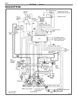
The EFI system is composed of three basic sub–systems: Fuel, Air Induction and Electronic Control Systems.
FUEL SYSTEM
Fuel is supplied under constant pressure to the EFI injectors by an electric fuel pump. The injectors inject
a metered quantity of fuel into the intake manifold in a accordance with signals from the ECU (Electronic Control
Unit).
AIR INDUCTION SYSTEM
The air induction system provides sufficient air for engine operation.
ELECTRONIC CONTROL SYSTEM
The ES250 2VZ–FE engines is equipped with a which centrally controls the EFI, ESA, ISC, Diagnosis systems
etc. by means of an Electronic Control Unit (ECU–formerly EFI computer) employing a microcomputer.
By means of the ECU, the controls the following functions:
1.
Electronic Fuel Injection (EFI)
The ECU receives signals from various sensors indicating changing engine operation conditions such as:
Intake air volume
Intake air temperature
Coolant temperature
Engine rpm
Acceleration/deceleration
Exhaust oxygen content etc.
The signals are utilized by the ECU to determine the injection duration necessary for an optimum air–fuel
ratio.
2.
Electronic Spark Advance (ESA)
The ECU is programmed with data for optimum ignition timing under any and all operating conditions.
Using data provided by sensors which monitor various engine functions (rpm, coolant temperature, etc.),
the microcomputer (ECU) triggers the spark at precisely the right instant. (See IG section)
3.
Idle Speed Control (ISC)
The ECU is programmed with target idling speed values to respond to different engine conditions (coolant
temperature, air conditioner ON/OFF, etc.). Sensors transmit signals to the ECU which control the flow of
air through the by–pass of the throttle valve and adjust idle speed to the target value. (See page
4. Diagnosis
The ECU detects any malfunctions abnormalties in the sensor network and lights a ”CHECK” engine warn-
ing light on the instrument panel. At the same time, the trouble is identified and a diagnostic code is re-
corded by the ECU. The diagnostic code can be read by the number of blinks of the ”CHECK” engine warn-
ing light when terminals TE1 and E1 are connected. The diagnostic codes are refer to the later page. (See
page
5. Fail–Safe
Function
In the event of the sensor malfunctioning, a back–up circuit will take over to provide minimal driveability,
and the ”CHECK” engine warning light will illuminate.
–
EFI SYSTEM
Description
FI–3
Summary of Contents for 2VZ-FE
Page 1: ...ENGINE MECHANICAL EM 1 ENGINE MECHANICAL Description Operation ...
Page 31: ...CYLINDER HEADS COMPONENTS EM 29 ENGINE MECHANICAL Cylinder Heads ...
Page 63: ...CYLINDER BLOCK REMOVAL OF ENGINE EM 61 ENGINE MECHANICAL Cylinder Block ...
Page 64: ...EM 62 ENGINE MECHANICAL Cylinder Block ...
Page 71: ...COMPONENTS EM 69 ENGINE MECHANICAL Cylinder Block ...
Page 106: ...EFI SYSTEM FI 1 ...
Page 107: ...DESCRIPTION FI 2 EFI SYSTEM Description ...
Page 111: ...OPERATION System Circuit FI 4 EFI SYSTEM Operation System Circuit ...
Page 121: ...FUEL SYSTEM Fuel Pump EFI SYSTEM Fuel System Fuel Pump FI 15 ...
Page 141: ...Fuel Tank and Lines COMPONENTS EFI SYSTEM Fuel System Fuel Tank and Lines FI 35 ...
Page 172: ...EXHAUST SYSTEM EXHAUST SYSTEM REPAIR INSTRUCTIONS EX 1 ...
Page 174: ...EMISSION CONTROL SYSTEMS EC 1 ...
Page 186: ...COOLING SYSTEM CO 1 ...
Page 205: ...LUBRICATION SYSTEM LUBRICATION SYSTEM Description Operation LU 1 ...
Page 224: ...IGNITION SYSTEM IG 1 ...
Page 237: ...SERVICE SPECIFICATIONS IG 14 IGNITION SYSTEM ServiceSpecifications ...
Page 238: ...ENGINE TROUBLESHOOTING TR 1 ...


