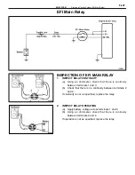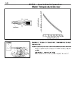
Circuit Opening Relay
INSPECTION OF CIRCUIT OPENING
RELAY
1. INSPECT
RELAY
CONTINUITY
(a) Using an ohmmeter, check that there is continuity
between terminals STA and E1.
(b) Check that there is continuity between terB and
FC.
(c) Check that there is no continuity between terB
and FP.
If continuity is not as specified, replace the relay.
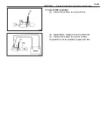
2. INSPECT
RELAY
OPERATION
(a) Apply battery voltage across terminals STA and E1.
(b) Using an ohmmeter, check that there is continuity
between terB and FP.
(c) Apply battery voltage across terB and FC.
(d) Check that there is continuity between terB and
FP.
If operation is not as specified, replace the relay.
FI–48
–
EFI SYSTEM
Electronic Control System (Circuit Opening Relay)
Summary of Contents for 2VZ-FE
Page 1: ...ENGINE MECHANICAL EM 1 ENGINE MECHANICAL Description Operation ...
Page 31: ...CYLINDER HEADS COMPONENTS EM 29 ENGINE MECHANICAL Cylinder Heads ...
Page 63: ...CYLINDER BLOCK REMOVAL OF ENGINE EM 61 ENGINE MECHANICAL Cylinder Block ...
Page 64: ...EM 62 ENGINE MECHANICAL Cylinder Block ...
Page 71: ...COMPONENTS EM 69 ENGINE MECHANICAL Cylinder Block ...
Page 106: ...EFI SYSTEM FI 1 ...
Page 107: ...DESCRIPTION FI 2 EFI SYSTEM Description ...
Page 111: ...OPERATION System Circuit FI 4 EFI SYSTEM Operation System Circuit ...
Page 121: ...FUEL SYSTEM Fuel Pump EFI SYSTEM Fuel System Fuel Pump FI 15 ...
Page 141: ...Fuel Tank and Lines COMPONENTS EFI SYSTEM Fuel System Fuel Tank and Lines FI 35 ...
Page 172: ...EXHAUST SYSTEM EXHAUST SYSTEM REPAIR INSTRUCTIONS EX 1 ...
Page 174: ...EMISSION CONTROL SYSTEMS EC 1 ...
Page 186: ...COOLING SYSTEM CO 1 ...
Page 205: ...LUBRICATION SYSTEM LUBRICATION SYSTEM Description Operation LU 1 ...
Page 224: ...IGNITION SYSTEM IG 1 ...
Page 237: ...SERVICE SPECIFICATIONS IG 14 IGNITION SYSTEM ServiceSpecifications ...
Page 238: ...ENGINE TROUBLESHOOTING TR 1 ...


