ELECTRONIC CONTROL SYSTEM
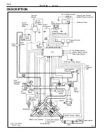
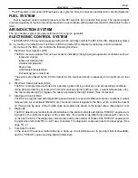
The control system consists of sensors which detect various engine conditions, and a ECU which determines
the injection volume (timing) based on the signals from the sensors.
The various sensors detect the intake air volume, engine rpm, oxygen density in the exhaust gas, coolant
temperature, intake air temperature and atmospheric pressure etc. and convert the information into an electrical
signal which is sent to the ECU. Based on these signals, the ECU calculates the optimum ignition timing for the
current conditions and operates the injectors.
The ECU not only controls the fuel injection timing, but also the self diagnostic function which records the
occurrence of a malfunction, ignition timing control, idle rpm control, EGR control, fuel pressure control and fuel
pump control.
–
EFI SYSTEM
Operation (System Operation)
FI–7
Summary of Contents for 2VZ-FE
Page 1: ...ENGINE MECHANICAL EM 1 ENGINE MECHANICAL Description Operation ...
Page 31: ...CYLINDER HEADS COMPONENTS EM 29 ENGINE MECHANICAL Cylinder Heads ...
Page 63: ...CYLINDER BLOCK REMOVAL OF ENGINE EM 61 ENGINE MECHANICAL Cylinder Block ...
Page 64: ...EM 62 ENGINE MECHANICAL Cylinder Block ...
Page 71: ...COMPONENTS EM 69 ENGINE MECHANICAL Cylinder Block ...
Page 106: ...EFI SYSTEM FI 1 ...
Page 107: ...DESCRIPTION FI 2 EFI SYSTEM Description ...
Page 111: ...OPERATION System Circuit FI 4 EFI SYSTEM Operation System Circuit ...
Page 121: ...FUEL SYSTEM Fuel Pump EFI SYSTEM Fuel System Fuel Pump FI 15 ...
Page 141: ...Fuel Tank and Lines COMPONENTS EFI SYSTEM Fuel System Fuel Tank and Lines FI 35 ...
Page 172: ...EXHAUST SYSTEM EXHAUST SYSTEM REPAIR INSTRUCTIONS EX 1 ...
Page 174: ...EMISSION CONTROL SYSTEMS EC 1 ...
Page 186: ...COOLING SYSTEM CO 1 ...
Page 205: ...LUBRICATION SYSTEM LUBRICATION SYSTEM Description Operation LU 1 ...
Page 224: ...IGNITION SYSTEM IG 1 ...
Page 237: ...SERVICE SPECIFICATIONS IG 14 IGNITION SYSTEM ServiceSpecifications ...
Page 238: ...ENGINE TROUBLESHOOTING TR 1 ...


