8
6
F
2
S
0
8
5
0
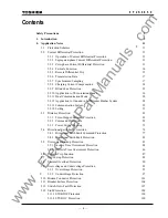
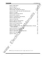
Appendix A Block Diagram
287
Appendix B Signal List
289
Appendix C Variable Timer List
323
Appendix D Binary Output Default Setting List
325
Appendix E Details of Relay Menu and LCD & Button Operation
329
Appendix F Case Outline
339
Appendix G Typical External Connection
347
Appendix H Relay Setting Sheet
351
Appendix I Commissioning Test Sheet (sample)
381
Appendix J Return Repair Form
387
Appendix K Technical Data
393
Appendix L Symbols Used in Scheme Logic
409
Appendix M Multi-phase Autoreclose
413
Appendix N Data Transmission Format
417
Appendix O Example of Setting
423
Appendix P Programmable Reset Characteristics and Implementation of Thermal
Model to IEC60255-8
435
Appendix Q IEC60870-5-103: interoperability
439
Appendix R Inverse Time Characteristics
453
Appendix S Failed Module Tracing and Replacement
457
Appendix S PLC Setting Sample
463
Appendix T Ordering
467
The data given in this manual are subject to change without notice. (Ver.0.3)
www
. ElectricalPartManuals
. com
Summary of Contents for GRL100-701B
Page 329: ... 328 6 F 2 S 0 8 5 0 w w w E l e c t r i c a l P a r t M a n u a l s c o m ...
Page 339: ... 338 6 F 2 S 0 8 5 0 w w w E l e c t r i c a l P a r t M a n u a l s c o m ...
Page 351: ... 350 6 F 2 S 0 8 5 0 w w w E l e c t r i c a l P a r t M a n u a l s c o m ...
Page 381: ... 380 6 F 2 S 0 8 5 0 w w w E l e c t r i c a l P a r t M a n u a l s c o m ...
Page 413: ... 412 6 F 2 S 0 8 5 0 w w w E l e c t r i c a l P a r t M a n u a l s c o m ...
Page 417: ... 416 6 F 2 S 0 8 5 0 w w w E l e c t r i c a l P a r t M a n u a l s c o m ...
Page 453: ... 452 6 F 2 S 0 8 5 0 w w w E l e c t r i c a l P a r t M a n u a l s c o m ...
Page 457: ... 456 6 F 2 S 0 8 5 0 w w w E l e c t r i c a l P a r t M a n u a l s c o m ...
Page 473: ...w w w E l e c t r i c a l P a r t M a n u a l s c o m ...


