218
6
F
2
S
0
8
5
0
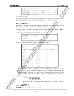
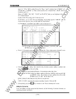
mode "A", "B" or "GPS", and the "Master" or "Slave", and "2 terminal line (=2TERM)" or "3
terminal line (=3TERM)" or "Dual communication for 2 terminal line (=Dual)". Refer to
Section 2 and 2.2.2.
However "TERM", "CH.CON", "T.SFT2" and "B.SYN2" items are not displayed in the case
of 2 terminal models.
For the "CH.CON" setting, refer to Section 2.2.14.
In
"B.SYN
∗
", set to "On" when synchronizing the sending signal of GRL100 with the
external clock signal or the receiving signal from multiplexer.
For "GPSBAK", "AUTO2B" and "SRC
θ
", refer to Section 2.2.7.
/ 6
S c h e m e
1 / 2
S P . S Y N
1 = M a s t
r
e
2 = S l
e
v
a
s w i t c h
1
T E R M
1 = 2 T E R M
2 = 3 T
M
R
E
1
.
3 = D u
l
a
C H . C O N
1 = N o r m
l
a
2 = E x
a
h
c
1
n g e
T . S F T 1
0 = O f f
1 = O n
1
T . S F T 2
0 = O f f
1 = O n
1
B . S Y N 1
0 = O f f
1 = O n
1
B . S Y N 2
0 = O f f
1 = O n
1
G P S
A K
0 = O f f
1 = O n
1
B
A U T
2 B
0 = O f f
1 = O n
0
O
S R C
0 = D i s a
l
b
1 = I
1
θ
e
R Y I
S V
0 = O f f
1 = O n
1
D
C O M M O D
1 = A
2
B
=
3 = G P S
2
E
1
Note: The setting of [COMMODE], [TERM], [GPSBAK], [AUTO2B], [SRC
θ
] and
[RYIDSV] must be identical at all terminals.
•
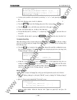
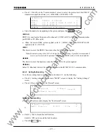
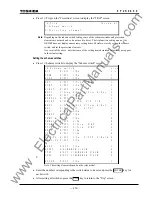
Press 2 (=Telecommunication element) to display the "Telecommunication element" screen.
/ 6
1 /
7
P
I
T
D
(
2
2 0
)
0
0
1
R Y
(
0
R Y
(
I
1
D
0 0
0
-
:
0
µ
0
)
3
6
-
:
0
)
3
6
-
:
0
T e l e c o m m u n i c a t
o
i
n
e l e m e n t
D
D
0
s
T
S
D
(
1
1 6 0
)
0
0
6 0
0 0 -
:
0
µ
0
V
s
R Y
(
I
2
D
)
3
6
-
:
0
0
T C D T 1
1
( -
0 0 0 0 -
u s
0
)
1 0 0 0 0
T C D T 2
1
( -
0 0 0 0 -
u s
0
)
1 0 0 0 0
:
:
•
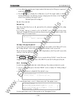
Enter the time delay setting values and the relay identity numbers (address numbers) and
press the ENTER key for each setting.
PDTD: Setting for permissible difference of telecommunication delay time.
RYID, RYID1, RYID2: Setting for address numbers of the local (RYID) and remote (RYID1
and RYID2) relays. These items are only enabled when the switch
[RYIDSV] is set to "ON". See Section 2.2.14.
TDSV: Setting for transmission delay time to be supervised.
TCDT1, TCDT2: Adjusting the transmission delay time for CH1 and CH2
•
After settings, press the END key to return to the "Telecommunication" screen.
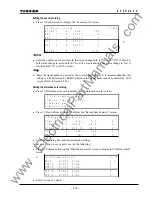
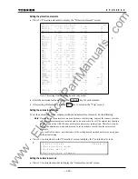
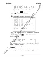
Setting the trip function
To set the scheme switches and protection elements, do the following. Protection elements are
measuring elements and timers.
www
. ElectricalPartManuals
. com
Summary of Contents for GRL100-701B
Page 329: ... 328 6 F 2 S 0 8 5 0 w w w E l e c t r i c a l P a r t M a n u a l s c o m ...
Page 339: ... 338 6 F 2 S 0 8 5 0 w w w E l e c t r i c a l P a r t M a n u a l s c o m ...
Page 351: ... 350 6 F 2 S 0 8 5 0 w w w E l e c t r i c a l P a r t M a n u a l s c o m ...
Page 381: ... 380 6 F 2 S 0 8 5 0 w w w E l e c t r i c a l P a r t M a n u a l s c o m ...
Page 413: ... 412 6 F 2 S 0 8 5 0 w w w E l e c t r i c a l P a r t M a n u a l s c o m ...
Page 417: ... 416 6 F 2 S 0 8 5 0 w w w E l e c t r i c a l P a r t M a n u a l s c o m ...
Page 453: ... 452 6 F 2 S 0 8 5 0 w w w E l e c t r i c a l P a r t M a n u a l s c o m ...
Page 457: ... 456 6 F 2 S 0 8 5 0 w w w E l e c t r i c a l P a r t M a n u a l s c o m ...
Page 473: ...w w w E l e c t r i c a l P a r t M a n u a l s c o m ...

