76
6
F
2
S
0
8
5
0
2.4 Directional Earth Fault Protection
For a high-resistance earth fault for which the impedance measuring elements cannot operate, the
GRL100 uses a directional earth fault element (DEF) to provide the following protections.
•
Directional earth fault command protection
•
Directional inverse or definite time earth fault backup protection
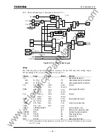
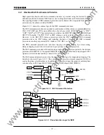
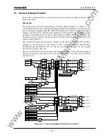
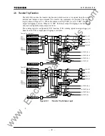
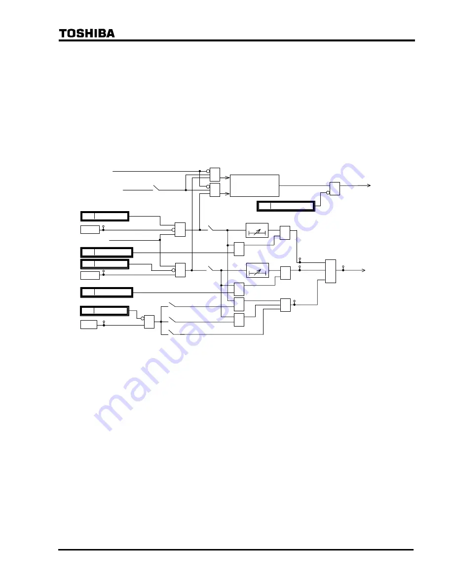
Figure 2.4.1 shows the scheme logic for the directional earth fault protection. The two kinds of
protection above can be enabled or disabled by the scheme switches [DEFCR], [CRSCM],
[DEFFEN] and [DEFREN]. The DEF command protection or DEF backup protection can be
blocked by the binary input signal (PLC signal) DEF
∗
_BLOCK or DEFCRT_BLOCK.
NON VTF
Command
Protection
&
CB-DISCR
&
M-TRIP
DEFR
DEFF
&
&
≥
1
[DEFFEN]
TDEF
t
0
0.00 - 10.00s
"ON"
[SCHEME]
S-TRIP
(from Figure 3.2.1.2.)
611
612
≥
1
[DEFREN]
TDER
t
0
0.00 - 10.00s
"ON"
[DEFCR]
"ON"
+
&
DEFF_INST_TP
1945
&
DEFR_INST_TP
1947
"
[EFIBT]
NOD "
" R "
F "
EFI
&
72
EFI_BLOCK
1592
&
&
"
≥
1
BU TRIP
(M-TRIP)
810
811
18
≥
1
DEFF_TRIP
DEFR_
TRIP
117
EFI_TRIP
DEFF_BLOCK
1897
DEFR_BLOCK
1899
&
DEFCRT_BLOCK
1875
Figure 2.4.1
Directional Earth Fault Protection
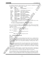
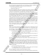
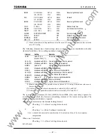
The directional earth fault command protection provides the POP, UOP and BOP schemes using
forward looking DEFF and reverse looking DEFR elements. All schemes execute three-phase
tripping and autoreclose.
The command protection is disabled during a single-phase autoreclosing period (CB-DISCR=1).
The directional earth fault protection as backup protection is described in Section 2.4.2.
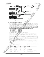
The directional earth fault element DEF provides selective protection against a high-resistance
earth fault. The direction of earth fault is determined by the lagging angle (
θ
) of the residual
current (3l0) with respect to the residual voltage (
−
3V0). The residual voltage and residual current
are derived from the vector summation of the three-phase voltages and three-phase currents inside
the relay.
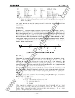
The phase angle
θ
in the event of an internal fault is equal to the angle of the zero-sequence
impedance of the system and in the directly-earthed system this value ranges approximately from
50
°
to 90
°
.
θ
of the DEF can be set from 0
°
to 90
°
. The minimum voltage necessary to maintain
directionality can be set from 1.7 to 21.0 V.
www
. ElectricalPartManuals
. com
Summary of Contents for GRL100-701B
Page 329: ... 328 6 F 2 S 0 8 5 0 w w w E l e c t r i c a l P a r t M a n u a l s c o m ...
Page 339: ... 338 6 F 2 S 0 8 5 0 w w w E l e c t r i c a l P a r t M a n u a l s c o m ...
Page 351: ... 350 6 F 2 S 0 8 5 0 w w w E l e c t r i c a l P a r t M a n u a l s c o m ...
Page 381: ... 380 6 F 2 S 0 8 5 0 w w w E l e c t r i c a l P a r t M a n u a l s c o m ...
Page 413: ... 412 6 F 2 S 0 8 5 0 w w w E l e c t r i c a l P a r t M a n u a l s c o m ...
Page 417: ... 416 6 F 2 S 0 8 5 0 w w w E l e c t r i c a l P a r t M a n u a l s c o m ...
Page 453: ... 452 6 F 2 S 0 8 5 0 w w w E l e c t r i c a l P a r t M a n u a l s c o m ...
Page 457: ... 456 6 F 2 S 0 8 5 0 w w w E l e c t r i c a l P a r t M a n u a l s c o m ...
Page 473: ...w w w E l e c t r i c a l P a r t M a n u a l s c o m ...

