278
6
F
2
S
0
8
5
0
•
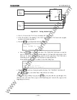
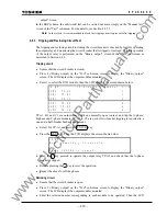
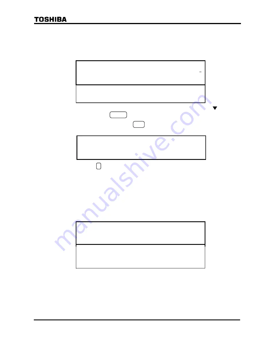
Press 3 (= Binary output) on the "Test" screen to display the "Binary output" screen. The
LCD displays the output modules installed depending on the model.
•
Enter 2 to select the IO#2 module, the LCD will display the screen shown below, indicating
the name of the module, the name of the output relay, the name of the terminal block and the
terminal number to which the relay contact is connected.
/ 3
B O
( 0 = D i s a b l e
1 = E n a b l e )
1 / 1 4
I O #
B O 1
0
I O #
B O 2
0
I O #
B O 3
0
.
.
O
B O 1
I #
1
2
2
2
2
3
•
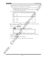
Move the cursor to the bottom line to select the BO13 output relay by pressing the key,
then enter 1 and press the ENTER key.
•
After completing the entries, press the END key. The LCD will display the screen shown
below.
/ 3
B O
K e e p
i n g
1 t o
o p e r a t e .
C A N C E
t o
c a n c e l .
L
P r e s s
p r e s s
•
Keep pressing the 1 key to operate the BO13 output relay forcibly. Then the BO13 output
contact will close. Monitor this at the telecommunication equipment.
The signal receive circuit from the telecommunication equipment to the relay is checked with the
"Binary input & output" screen on the LCD as follows:
Note:
The receive signal is assigned to any of the binary inputs by the user setting. The following
description is the case of BIn and BIm assigned.
•
Display the "Binary I/O" screen from the "Status" sub-menu. Position BIm indicates a
receive signal status. Position BIn indicates the status of the guard signal in case of
frequency shift signaling.
/ 2 B i n a r y i n p u t
&
o u t p u t
3 / 8
I n p u t ( I
O
# 1
[ 0 0 0
0 0 0
0 0 0
0 0 0 0 0 0 ]
I n p u t
( I
O
# 2
[ 0 0 0
]
O u t p u t ( I
O
1 - t r i p )
[ 0 0 0
0 0 0
]
O u t p u t ( I
O
# 3
[ 0 0 0
0 0 0
0 0 0
0
]
O u t p u t ( I
O
# 4
[ 0 0 0
0 0 0
0 0 0
0 0 0
0 0
]
)
)
O u t p u t ( I
O
# 2
[ 0 0 0
0 0 0
0 0 0
0 0 0
0 0
]
I n p u t
( I
O
# 3
[ 0 0 0
0 0 0
0 0 0
0
]
)
)
)
)
#
I n p u t
( I
O
# 4
[ 0 0 0
]
)
•
Send a signal or interrupt sending a signal at the telecommunication equipment and monitor
on the screen that the status of BIn or BIm changes accordingly.
If the signaling circuit connection is completed from the local relay to the remote relay, the test
above can be extended to an end-to-end test.
•
Send the signal by operating the BO13 output relay at one end with the "Test" sub-menu as
described above and monitor the signal reception at the other end on the "Binary input &
www
. ElectricalPartManuals
. com
Summary of Contents for GRL100-701B
Page 329: ... 328 6 F 2 S 0 8 5 0 w w w E l e c t r i c a l P a r t M a n u a l s c o m ...
Page 339: ... 338 6 F 2 S 0 8 5 0 w w w E l e c t r i c a l P a r t M a n u a l s c o m ...
Page 351: ... 350 6 F 2 S 0 8 5 0 w w w E l e c t r i c a l P a r t M a n u a l s c o m ...
Page 381: ... 380 6 F 2 S 0 8 5 0 w w w E l e c t r i c a l P a r t M a n u a l s c o m ...
Page 413: ... 412 6 F 2 S 0 8 5 0 w w w E l e c t r i c a l P a r t M a n u a l s c o m ...
Page 417: ... 416 6 F 2 S 0 8 5 0 w w w E l e c t r i c a l P a r t M a n u a l s c o m ...
Page 453: ... 452 6 F 2 S 0 8 5 0 w w w E l e c t r i c a l P a r t M a n u a l s c o m ...
Page 457: ... 456 6 F 2 S 0 8 5 0 w w w E l e c t r i c a l P a r t M a n u a l s c o m ...
Page 473: ...w w w E l e c t r i c a l P a r t M a n u a l s c o m ...

