216
6
F
2
S
0
8
5
0
/ 7
S e t t i n g i m
( G r o u p
* )
1 = S y m m e
p e d a n
e
c
p
2 = P h a s e i m e d a
e
c
n
m o
e
d
i m p e d a n
e
c
C u r r e n t
N o . =
1
S e l e c t
N o .
=
t r i c a l
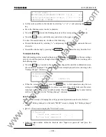
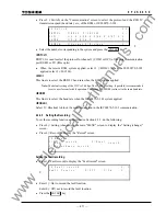
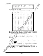
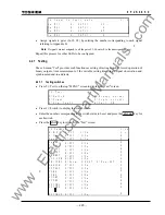
One of the setting modes can be selected.
•
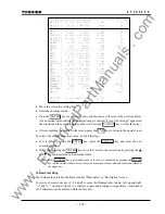
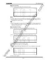
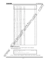
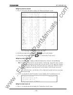
Select 1 (=Symmetrical impedance), then the following "Line data" screen is displayed.
/ 7
L i n e
a
a
t
1 /
*
*
1
L
(
0 .
9 9 .
)
9
9
(
0
9
(
0
(
0
(
(
d
Z O B -
B
Z 0
(
0 0
. 0 0
. 0
- 1
:
.
Ω
5
9 9 .
)
9
9
4
- 1
:
.
Ω
0
9 9 .
)
9
9
2
-
0
:
.
3
Ω
0
0 .
9 9 .
)
9
9
4
0
3
0
0 0
. 0 0
. 0
- 1
:
.
Ω
0
9 9 .
)
9
9
0
- 1
:
.
Ω
7
9 9 .
)
9
9
0
-
1
:
.
0
Ω
0
0 .
0
0 0
-
:
.
Ω
0
9 9 .
)
9
9
1
K
b
a
(
1
)
0
2
8 0
0
-
:
1
%
0
(
L i n e
0
3 9 9
)
9
.
0
-
8
:
.
m
k
0
0
0
0
1
0
- R
1
0
K
c
b
(
1
)
0
2
8 0
0
-
:
1
%
0
K
a
c
(
1
)
0
2
8 0
0
-
:
1
%
0
K a
(
1
)
0
2
8 0
0
-
:
1
%
0
K b
(
1
)
0
2
8 0
0
-
:
1
%
0
K c
(
1
)
0
2
8 0
0
-
:
1
%
0
1
1 R
(
0
0
. 0
9 9 .
)
9
9
0
-
0
:
.
Ω
0
0
1
2 X
(
0 .
9 9 .
)
9
9
0
9
0 0
- 1
:
.
Ω
5
1
2 R
(
0 .
9 9 .
)
9
9
4
3
0 0
- 1
:
.
Ω
0
1
(
2 L i n
0 . 0
3 9 9
)
9
.
0
-
4
:
.
m
k
0
e
3 X
(
0 .
9 9 .
)
9
9
0
9
0 0
- 1
:
.
Ω
5
1
3 R
(
0 .
9 9 .
)
9
9
4
3
0 0
- 1
:
.
Ω
0
1
(
3 L i n
0 . 0
3 9 9
)
9
.
0
-
2
:
.
m
k
0
e
1
m
1 X 1
1 X 0
1 X 0
1 R 1
1 R 0
m
0 .
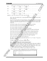
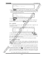
In case of two-terminal lines, enter the reactive and resistive component of the symmetrical line
impedance to the items 1X1 and 1R1 and line length to 1 Line. Press the enter key for each entry.
Note:
The line impedance is input with the secondary value.
In case of three-terminal lines, enter the data on the first section from the local terminal to the
junction to the items expressed as 1
∗∗
, the data on the second section from the junction to the
remote terminal 1 to 2
∗∗
and the data on the third section from the junction to the remote
terminal 2 to 3
∗∗
.
•
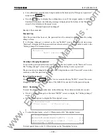
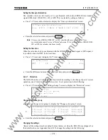
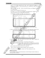
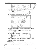
Select 2 (=Phase impedance), then the following "Line data" screen is displayed.
In case of two-terminal lines, enter the reactive and resistive component of the self-impedances
and mutual-impedances of the line to the items expressed as 1X
∗∗
and 1R
∗∗
and line length to 1
Line. Press the ENTER key for each entry.
In case of three-terminal lines, enter the data on the first section from the local terminal to the
junction to 1
∗∗∗
, the data on the second section from the junction to the remote terminal 1 to
2
∗∗∗
and the data on the third section from the junction to the remote terminal 2 to 3
∗∗∗
.
•
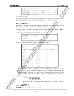
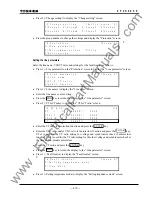
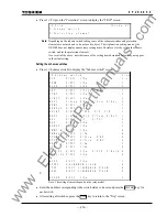
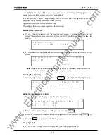
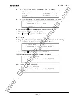
Press the END key after completing the settings to return the display to the "Line
parameter" screen
www
. ElectricalPartManuals
. com
Summary of Contents for GRL100-701B
Page 329: ... 328 6 F 2 S 0 8 5 0 w w w E l e c t r i c a l P a r t M a n u a l s c o m ...
Page 339: ... 338 6 F 2 S 0 8 5 0 w w w E l e c t r i c a l P a r t M a n u a l s c o m ...
Page 351: ... 350 6 F 2 S 0 8 5 0 w w w E l e c t r i c a l P a r t M a n u a l s c o m ...
Page 381: ... 380 6 F 2 S 0 8 5 0 w w w E l e c t r i c a l P a r t M a n u a l s c o m ...
Page 413: ... 412 6 F 2 S 0 8 5 0 w w w E l e c t r i c a l P a r t M a n u a l s c o m ...
Page 417: ... 416 6 F 2 S 0 8 5 0 w w w E l e c t r i c a l P a r t M a n u a l s c o m ...
Page 453: ... 452 6 F 2 S 0 8 5 0 w w w E l e c t r i c a l P a r t M a n u a l s c o m ...
Page 457: ... 456 6 F 2 S 0 8 5 0 w w w E l e c t r i c a l P a r t M a n u a l s c o m ...
Page 473: ...w w w E l e c t r i c a l P a r t M a n u a l s c o m ...

