12
6
F
2
S
0
8
5
0
2.2 Current Differential Protection
GRL100 is applicable to telecommunication systems which employ dedicated optical fibre, 64 kbit/s
multiplexed communication channels or microwave links.
2.2.1 Operation of Current Differential Protection
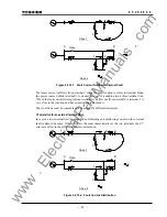
Current differential protection compares the currents flowing into and out of the protected line.
The difference of the currents, that is, the differential current, is almost zero when a fault is
external or there is no fault, and is equal to the fault current when the fault is internal. The
differential protection operates when the difference of the currents exceeds a set value.
The GRL100 relay installed at each line terminal samples the local currents every 7.5 electrical
degrees and transmits the current data to other terminals every four samples via the
telecommunication system. The GRL100 performs master/master type current differential
protection using the current data from all terminals.
As synchronized sampling of all terminals is performed in the GRL100, the current data are the
instantaneous values sampled simultaneously at each terminal. Therefore, the differential current
can be easily calculated by summing the local and remote current data with the identical
sampling address. Thus, compensation of transmission delay time is not required.
The GRL100 utilises the individual three phase currents and residual current to perform
segregated-phase and zero-phase current differential protection.
2.2.2 Segregated-phase Current Differential Protection
The segregated-phase differential protection transmits the three phase currents to the remote
terminal, calculates the individual differential currents and detects both phase-to-phase and
phase-to-earth faults on a per phase basis.
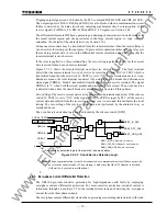
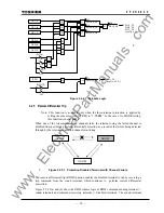
Figure 2.2.2.1 shows the scheme logic of the segregated-phase current differential protection.
Output signals of differential elements DIF-A, -B and -C can perform instantaneous tripping of
the breaker on a per phase basis and start the incorporated autoreclose function.
Note
: For the symbols used in the scheme logic, see Appendix L.
DIF.FS-A_TP
DIF.FS-B_TP
DIF.FS-C_TP
DIF-A
&
41
&
82: DIF-A_TRIP
&
401
DIF-B
&
42
&
83: DIF-B_TRIP
&
DIF-C
&
Communication
failure, etc.
43
&
1
CRT_BLOCK
1544
84: DIF-C_TRIP
&
DIF-A_FS
1616
DIF-B_FS
1617
DIF-C_FS
1618
403
402
≥
1
400
DIF.FS_TRIP
43C ON
&
TELEPROTECTION OFF
(from IEC103 command)
DIFFS
1
DIF_BLOCK
1585
DIF BLOCK
Figure 2.2.2.1 Scheme Logic of Segregated-phase Current Differential Protection
www
. ElectricalPartManuals
. com
Summary of Contents for GRL100-701B
Page 329: ... 328 6 F 2 S 0 8 5 0 w w w E l e c t r i c a l P a r t M a n u a l s c o m ...
Page 339: ... 338 6 F 2 S 0 8 5 0 w w w E l e c t r i c a l P a r t M a n u a l s c o m ...
Page 351: ... 350 6 F 2 S 0 8 5 0 w w w E l e c t r i c a l P a r t M a n u a l s c o m ...
Page 381: ... 380 6 F 2 S 0 8 5 0 w w w E l e c t r i c a l P a r t M a n u a l s c o m ...
Page 413: ... 412 6 F 2 S 0 8 5 0 w w w E l e c t r i c a l P a r t M a n u a l s c o m ...
Page 417: ... 416 6 F 2 S 0 8 5 0 w w w E l e c t r i c a l P a r t M a n u a l s c o m ...
Page 453: ... 452 6 F 2 S 0 8 5 0 w w w E l e c t r i c a l P a r t M a n u a l s c o m ...
Page 457: ... 456 6 F 2 S 0 8 5 0 w w w E l e c t r i c a l P a r t M a n u a l s c o m ...
Page 473: ...w w w E l e c t r i c a l P a r t M a n u a l s c o m ...


