52
6
F
2
S
0
8
5
0
Zone 1 setting
Since instantaneous tripping is allowed in zone 1, it is desirable to select a setting that will cover
the widest possible range of the protected line. Conversely, zone 1 elements must not respond to
faults further than the remote end. Therefore, the setting of the zone 1 reach is set to 80 to 90% of
the impedance of the protected line taking account of VT and CT errors and measurement error.
The reach is set on the X-axis.
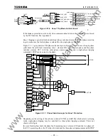
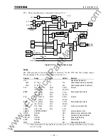
In order to change the reactance element characteristic into a broken line, Z1S(G)
θ
1 and
Z1S(G)
θ
2 in Figure 2.3.1.1 or Figure 2.3.1.2 must be set.
Time delayed tripping of zone 1 is selected when instantaneous tripping by another main
protection is given priority. The time delay TZ1 is set to ensure that coordination is maintained
with fault clearance by the main protection. Suppose that the maximum operating time of the main
protection is Tp, the opening time of the circuit breaker is Tcb, the minimum operating time of
zone 1
element is T1 and the reset time of the zone 1 element is Tzone 1, then TZ1 must satisfy
the following condition:
TZ1 > Tp + Tcb + Tzone 1
−
T1
Zone 2 setting
Zone 2 is required to cover 10 to 20% of the remote end zone not covered by zone 1. To assure this
protection, it is set to 120% or greater of the protected line impedance. To maintain the selectivity
with zone 1 of the adjacent lines, the zone 2 reach should not exceed the zone 1 reach of the
shortest adjacent line. The reach is set on the X-axis.
Time delay TZ2 is set so that it may be coordinated with fault clearance afforded by the main
protection of the adjacent lines. If time delayed tripping is selected for zone 1 of the protected line,
coordination with the time delay should also be taken into account. Suppose that the main
protection operating time on the adjacent lines is Tp', the opening time of the circuit breaker is
Tcb', the minimum operating time of zone 2 element is T2 and the reset time of local terminal zone
2 element is Tzone 2, then TZ2 must satisfy the following two conditions:
TZ2 > Tp' + Tcb' + Tzone 2
−
T2
TZ2 > TZ1
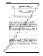
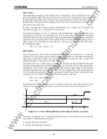
If the adjacent lines are too short for zone 2 to coordinate with zone 1 of the adjacent lines in reach
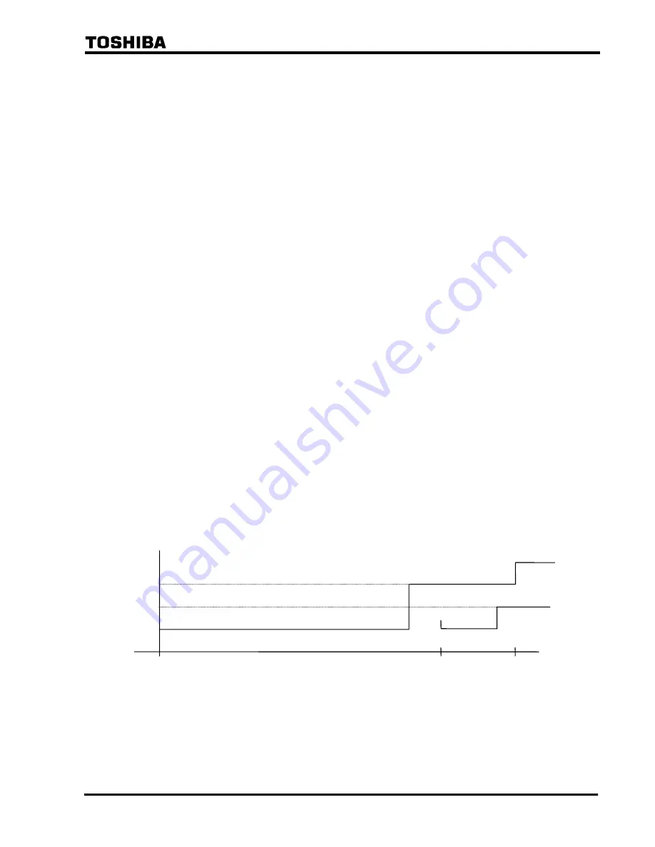
setting, it is necessary to set a much greater time delay for zone 2 as shown in Figure 2.3.1.9.
Figure 2.3.1.9 Zone 2 Setting (When one of the adjacent lines is very short)
Generally, in setting the zone 2, consideration should be given to ensure selectivity with even the
slowest timer of the following protections:
•
Remote end busbar protection
•
Remote end transformer protection
Time
T2'
T2
Zone 3
Zone 2
Zone 2
Zone 1
Zone 1
C
B
A
www
. ElectricalPartManuals
. com
Summary of Contents for GRL100-701B
Page 329: ... 328 6 F 2 S 0 8 5 0 w w w E l e c t r i c a l P a r t M a n u a l s c o m ...
Page 339: ... 338 6 F 2 S 0 8 5 0 w w w E l e c t r i c a l P a r t M a n u a l s c o m ...
Page 351: ... 350 6 F 2 S 0 8 5 0 w w w E l e c t r i c a l P a r t M a n u a l s c o m ...
Page 381: ... 380 6 F 2 S 0 8 5 0 w w w E l e c t r i c a l P a r t M a n u a l s c o m ...
Page 413: ... 412 6 F 2 S 0 8 5 0 w w w E l e c t r i c a l P a r t M a n u a l s c o m ...
Page 417: ... 416 6 F 2 S 0 8 5 0 w w w E l e c t r i c a l P a r t M a n u a l s c o m ...
Page 453: ... 452 6 F 2 S 0 8 5 0 w w w E l e c t r i c a l P a r t M a n u a l s c o m ...
Page 457: ... 456 6 F 2 S 0 8 5 0 w w w E l e c t r i c a l P a r t M a n u a l s c o m ...
Page 473: ...w w w E l e c t r i c a l P a r t M a n u a l s c o m ...


