185
6
F
2
S
0
8
5
0
4. User Interface
4.1 Outline of User Interface
The user can access the relay from the front panel.
Local communication with the relay is also possible using a personal computer (PC) via an
RS232C port. Furthermore, remote communication is also possible using RSM (Relay Setting
and Monitoring) or IEC60870-5-103 communication, etc., via an RS485.
This section describes the front panel configuration and the basic configuration of the menu tree
of the local human machine communication ports and HMI (Human Machine Interface).
4.1.1 Front
Panel
As shown in Figure 3.1.5.1, the front panel is provided with a liquid crystal display (LCD), light
emitting diode (LED), operation keys, VIEW and RESET keys, monitoring jack and
RS232C connector.
LCD
The LCD screen, provided with a 4-line, 40-character back-light, displays detailed information
of the relay interior such as records, status and settings. The LCD screen is normally unlit, but
pressing the VIEW key will display the digest screen and pressing any key other than VIEW
and RESET will display the menu screen.
These screens are turned off by pressing the RESET key or END key. If any display is left for
5 minutes or longer without operation, the back-light will go off.
LED
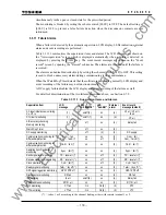
There are 8 LED displays. The signal labels and LED colors are defined as follows:
Label Color Remarks
IN SERVICE
Green
Lit when the relay is in service.
TRIP Red
Lit when a trip command is issued.
ALARM Red
Lit when a failure is detected.
TESTING Red
Lit when the testing switches are in test
position.
(LED1)
Red
Configurable LED to assign signals with or without latch
when relay operates.
(LED2)
Red
Configurable LED to assign signals with or without latch
when relay operates.
(LED3)
Red
Configurable LED to assign signals with or without latch
when relay operates.
(LED4)
Red
Configurable LED to assign signals with or without latch
when relay operates.
The TRIP LED lights up once the relay is operating and remains lit even after the trip command
goes off. For the operation, see Section 4.2.1.
www
. ElectricalPartManuals
. com
Summary of Contents for GRL100-701B
Page 329: ... 328 6 F 2 S 0 8 5 0 w w w E l e c t r i c a l P a r t M a n u a l s c o m ...
Page 339: ... 338 6 F 2 S 0 8 5 0 w w w E l e c t r i c a l P a r t M a n u a l s c o m ...
Page 351: ... 350 6 F 2 S 0 8 5 0 w w w E l e c t r i c a l P a r t M a n u a l s c o m ...
Page 381: ... 380 6 F 2 S 0 8 5 0 w w w E l e c t r i c a l P a r t M a n u a l s c o m ...
Page 413: ... 412 6 F 2 S 0 8 5 0 w w w E l e c t r i c a l P a r t M a n u a l s c o m ...
Page 417: ... 416 6 F 2 S 0 8 5 0 w w w E l e c t r i c a l P a r t M a n u a l s c o m ...
Page 453: ... 452 6 F 2 S 0 8 5 0 w w w E l e c t r i c a l P a r t M a n u a l s c o m ...
Page 457: ... 456 6 F 2 S 0 8 5 0 w w w E l e c t r i c a l P a r t M a n u a l s c o m ...
Page 473: ...w w w E l e c t r i c a l P a r t M a n u a l s c o m ...

