332
6
F
2
S
0
8
5
0
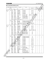
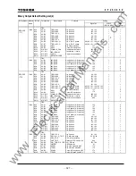
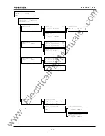
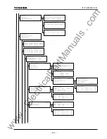
/2 Status
1=Metering
2=Time Synchronization
3=Time zone
/3 Time synchronization 1/ 1
Sync 0=Off 1=IRIG 2=RSM 3=IEC 4=GPS 1
/3 Time zone 1/ 1
GMT ( +9 hrs )
/3 Metering 3/ 3
Display value 1=Primary 2=Secondary 1
Power (P/Q) 1=Send 2=Receive 1
Current 1=Lag 2=Lead 1
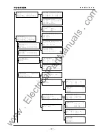
/4 Line parameter (Group 1)
1=Line name
2=VT & CT ratio
3=Fault locator
/4 Telecommunication (Group 1)
1=Scheme switch
2=Telecommunication element
/6 Line data 3/ 5
1X1 ( 24.5
Ω
) 1R1 ( 2.8
Ω
)
1Line ( 80.0km) 2X1 ( 12.5
Ω
)
2R1 ( 1.5
Ω
) 2Line ( 41.3km)
/5 Scheme switch 2/ 12
COMMODE 1=A 2=B 3=GPS 2
SP.SYN. 1=Master 2=Slave 1
TERM. 1=2TERM 2=3TERM 3=Dual 1 _
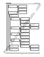
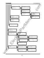
/2 Protection (Active group= *)
1=Group1 2=Group2 3=Group3 4=Group4
5=Group5 6=Group6 7=Group7 8=Group8
/5 Line name 1/ 1
Line name ********************
/3 Protection (Group 1)
1=Line parameter
2=Telecommunication 3=Trip
4=Autoreclose
/5 VT & CT ratio 1/ 2
VT ( 2000 ) VTs1 ( 2000 )
VTs2 ( 2000 ) CT ( 120 )
/5 Scheme switch 3/16
TPMODE 1=3PH 2=1PH 3=MPH 1
STUB 0=Off 1=On 1
DIFG 0=Off 1=On 1
/5 Protection element
3/11
DIFI1 ( 1.00A ) DIFI2 ( 2.0A )
DIFG1 ( 0.50A ) DIFIC ( 1.00A )
Vn ( 110V ) TDIFG ( 0.10s )
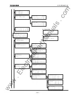
/4 Autoreclose (Group 1)
1=Autoreclose mode
2=Scheme switch
3=Autoreclose element
/5 Scheme switch 3/ 8
ARC-CB 1=00 2=01 3=02 4=L1 5=L2 1
ARC-EXT 0=Off 1=On 0
ARCDIFG 0=Off 1=On 1
/5 Autoreclose element (Group 1)
1=Autoreclose timer
2=Synchrocheck
/6 Autoreclose timer 3/ 8
TEVLV( 0.30 s ) TRDY1( 60 s )
TSPR ( 0.80 s ) TTPR1( 0.60 s )
TRR ( 2.00 s ) TW1 ( 0.3 s )
/6 Synchrocheck 3/ 9
OVB ( 51 V ) UVB ( 13 V )
OVL1 ( 51 V ) UVL1 ( 13 V )
SY1UV( 83 V ) SY1OV( 51 V )
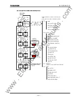
/5 Autoreclose mode
1=Disable 2=SPAR 3=TPAR 4=SPAR&TPAR
5=MPAR2 6=MPAR3 7=EXT1P 8=EXT3P 9=EXTMP
Current No.= 4
/3 Protection (Group 8)
1=Line parameter
2=Telecommunication 3=Trip
4=Autoreclose
/3 Protection (Group 2)
1=Line parameter
2=Telecommunication 3=Trip
4=Autoreclose
a-1 a-2
a-1 a-2
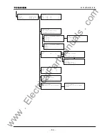
/4 Trip (Group 1)
1=Scheme switch
2=Protection element
/5 Telecommunicatio element 1/ 7
PDTD ( 200 - 2000) : 1000 us
RYID ( 0 - 63) : 0
RYID1 ( 0 - 63) : 0
/5 Fault locator (Group 1)
1=Setting impedance mode
2=Line data
/6 Setting impedance mode
1=Symmetrical impedance
2=Phase impedance
Current No.= 1
www
. ElectricalPartManuals
. com
Summary of Contents for GRL100-701B
Page 329: ... 328 6 F 2 S 0 8 5 0 w w w E l e c t r i c a l P a r t M a n u a l s c o m ...
Page 339: ... 338 6 F 2 S 0 8 5 0 w w w E l e c t r i c a l P a r t M a n u a l s c o m ...
Page 351: ... 350 6 F 2 S 0 8 5 0 w w w E l e c t r i c a l P a r t M a n u a l s c o m ...
Page 381: ... 380 6 F 2 S 0 8 5 0 w w w E l e c t r i c a l P a r t M a n u a l s c o m ...
Page 413: ... 412 6 F 2 S 0 8 5 0 w w w E l e c t r i c a l P a r t M a n u a l s c o m ...
Page 417: ... 416 6 F 2 S 0 8 5 0 w w w E l e c t r i c a l P a r t M a n u a l s c o m ...
Page 453: ... 452 6 F 2 S 0 8 5 0 w w w E l e c t r i c a l P a r t M a n u a l s c o m ...
Page 457: ... 456 6 F 2 S 0 8 5 0 w w w E l e c t r i c a l P a r t M a n u a l s c o m ...
Page 473: ...w w w E l e c t r i c a l P a r t M a n u a l s c o m ...

