182
6
F
2
S
0
8
5
0
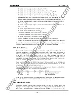
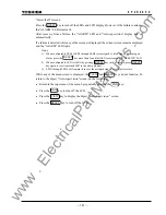
- Magnitude and phase angle of phase voltage (Va, Vb, Vc)
- Magnitude and phase angle of phase current at the local terminal (Ia, Ib, Ic)
- Magnitude and phase angle of phase voltage for autoreclose (Vs1, Vs2)
- Magnitude and phase angle of symmetrical component voltage (V1, V2, V0)
- Magnitude and phase angle of symmetrical component current at the local terminal (I1, I2, I0)
- Magnitude and phase angle of positive sequence voltage at the remote terminal 1 and 2 (V11, V12)
- Magnitude and phase angle of phase current and residual current at the remote terminal 1
(Ia1, Ib1, Ic1, I01)
- Magnitude and phase angle of phase current and residual current at the remote terminal 2
(Ia2, Ib2, Ic2, I02)
- Magnitude of phase differential current (Ida, Idb, Idc)
- Magnitude of residual differential current (Id0)
- Telecommunication delay time 1 at the remote terminal 1
- Telecommunication delay time 2 at the remote terminal 2
- Magnitude of parallel line zero sequence current (I0m)
- Resistive and reactive component of phase impedance (Ra, Rb, Rc, Xa, Xb, Xc)
- Resistive and reactive component of phase-to-phase impedance (Rab, Rbc, Rca, Xab, Xbc, Xca)
Phase angles above are expressed taking that of positive sequence voltage or positive sequence
current when the voltage is small or no voltage is input) as a reference phase angle.
3.4.2 Event
Recording
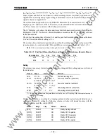
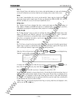
The events shown are recorded with a 1 ms resolution time-tag when the status changes. The user
can set the maximum 128 recording items and their status change mode. The event recording is
initiated by a binary input signal. The event items can be assigned to a signal number in the
signal list. The status change mode is set to “On” (only recording when On.) or
“On/Off”(recording when both On and Off.) mode by setting. The items of “On/Off” mode are
specified by “Bi-trigger events” setting. If the “Bi-trigger events” is set to “100”, No.1 to 100
events are “On/Off” mode and No.101 to 128 events are “On” mode.
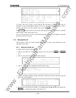
The name of event can be set by RSM100. Maximum 22 characters can be set, but LCD displays
up to 11 characters of them. Therefore, it is recommended the maximum characters are set. The
set name can be viewed on the Setting(view) screen.
The elements necessary for event recording and their setting ranges are shown in the table below.
The default setting of event record is shown in Appendix H.
Element Range Step
Default
Remarks
BITRN
0 - 128
1
100
Number of bi-trigger(on/off) events
EV1 – EV128
0 - 3071
Assign the signal number
Up to 480 records can be stored. If an additional event occurs when 480 records have been
stored, the oldest event record is deleted and the latest event record is then stored.
3.4.3 Disturbance
Recording
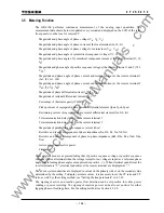
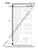
Disturbance recording is started when overcurrent or undervoltage starter elements operate or a
tripping command is output, or PLC command by user-setting (max. 4: Signal No. 2632 to 2635)
is outputted. The records include 19 analog signals (local terminal: Va, Vb, Vc, Ia, Ib, Ic, 3I0,
www
. ElectricalPartManuals
. com
Summary of Contents for GRL100-701B
Page 329: ... 328 6 F 2 S 0 8 5 0 w w w E l e c t r i c a l P a r t M a n u a l s c o m ...
Page 339: ... 338 6 F 2 S 0 8 5 0 w w w E l e c t r i c a l P a r t M a n u a l s c o m ...
Page 351: ... 350 6 F 2 S 0 8 5 0 w w w E l e c t r i c a l P a r t M a n u a l s c o m ...
Page 381: ... 380 6 F 2 S 0 8 5 0 w w w E l e c t r i c a l P a r t M a n u a l s c o m ...
Page 413: ... 412 6 F 2 S 0 8 5 0 w w w E l e c t r i c a l P a r t M a n u a l s c o m ...
Page 417: ... 416 6 F 2 S 0 8 5 0 w w w E l e c t r i c a l P a r t M a n u a l s c o m ...
Page 453: ... 452 6 F 2 S 0 8 5 0 w w w E l e c t r i c a l P a r t M a n u a l s c o m ...
Page 457: ... 456 6 F 2 S 0 8 5 0 w w w E l e c t r i c a l P a r t M a n u a l s c o m ...
Page 473: ...w w w E l e c t r i c a l P a r t M a n u a l s c o m ...


