183
6
F
2
S
0
8
5
0
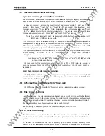
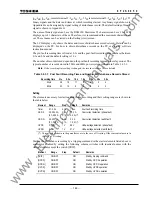
Ida, Idb, Idc, Id0, remote terminal 1: Ia1, Ib1, Ic1, 3I01 remote terminal 2: Ia2, Ib2, Ic2, 3I02), 32
binary signals and the dates and times at which recording started. Any binary signal shown in
Appendix B can be assigned by signal setting of disturbance record. The default setting of binary
signal is shown in Appendix H.
The name of binary signal can be set by RSM100. Maximum 22 characters can be set, but LCD
displays up to 11 characters of them. Therefore, it is recommended the maximum characters are
set. The set name can be viewed on the Setting(view) screen.
The LCD display only shows the dates and times of disturbance records stored. Details can be
displayed on the PC. For how to obtain disturbance records on the PC, see the PC software
instruction manual.
The pre-fault recording time is fixed at 0.3s and the post-fault recording time can be set between
0.1 and 3.0s and the default setting is 1.0s.
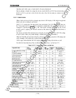
The number of records stored depends on the post-fault recording time and the relay model. The
typical number of records stored in 50Hz and 60Hz power system is shown in Table 3.4.3.1.
Note:
If the recording time setting is changed, the records stored so far are deleted.
Table 3.4.3.1 Post Fault Recording Time and Number of Disturbance Records Stored
Recording
time 0.1s 0.5s 1.0s 1.5s 2.0s 2.5s 3.0s
50Hz
36 18 11 8 6 5 4
60Hz 30 15 9 6 5 4 3
Setting
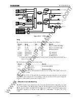
The elements necessary for starting disturbance recording and their setting ranges are shown in
the table below.
Element Range
Step Default Remarks
Timer
0.1-3.0 s
0.1 s
1.0 s
Post-fault recording time
OCP-S 0.5-250.0
A
(0.1-50.0 A
0.1 A
0.1 A
10.0 A
2.0 A) (*)
Overcurrent detection (phase fault)
OCP-G 0.5-250.0
A
(0.1-50.0 A
0.1 A
0.1 A
5.0 A
1.0 A) (*)
Overcurrent detection (earth fault)
UVP-S
0-132 V
1 V
88 V
Undervoltage detection (phase fault)
UVP-G
0-76 V
1 V
51 V
Undervoltage detection (earth fault)
(*) Current values shown in the parentheses are in the case of 1A rating. Other current values are in
the case of 5A rating.
Starting the disturbance recording by a tripping command or the starter elements listed above is
enabled or disabled by setting the following scheme switches with identical names with the
starter elements except the switch [TRIP].
Element Range Step Default Remarks
[TRIP]
ON/OFF
ON
Start by tripping command
[OCP-S]
ON/OFF
ON
Start by OCP-S operation
[OCP-G]
ON/OFF
ON
Start by OCP-G operation
[UVP-S]
ON/OFF
ON
Start by UVP-S operation
[UVP-G]
ON/OFF
ON
Start by UVP-G operation
www
. ElectricalPartManuals
. com
Summary of Contents for GRL100-701B
Page 329: ... 328 6 F 2 S 0 8 5 0 w w w E l e c t r i c a l P a r t M a n u a l s c o m ...
Page 339: ... 338 6 F 2 S 0 8 5 0 w w w E l e c t r i c a l P a r t M a n u a l s c o m ...
Page 351: ... 350 6 F 2 S 0 8 5 0 w w w E l e c t r i c a l P a r t M a n u a l s c o m ...
Page 381: ... 380 6 F 2 S 0 8 5 0 w w w E l e c t r i c a l P a r t M a n u a l s c o m ...
Page 413: ... 412 6 F 2 S 0 8 5 0 w w w E l e c t r i c a l P a r t M a n u a l s c o m ...
Page 417: ... 416 6 F 2 S 0 8 5 0 w w w E l e c t r i c a l P a r t M a n u a l s c o m ...
Page 453: ... 452 6 F 2 S 0 8 5 0 w w w E l e c t r i c a l P a r t M a n u a l s c o m ...
Page 457: ... 456 6 F 2 S 0 8 5 0 w w w E l e c t r i c a l P a r t M a n u a l s c o m ...
Page 473: ...w w w E l e c t r i c a l P a r t M a n u a l s c o m ...

