275
6
F
2
S
0
8
5
0
[PSB-Z2], [-Z3] and [-ZR].
Check that power swing blocking is recorded on the event record.
Out-of-step tripping
Set the scheme switch [OST] to "Trip".
Shift the phase angle from the second quadrant to the third quadrant or vice versa taking the
remote terminal voltage as a reference voltage.
Check that the tripping output relay operates in all phases and autoreclose does not start.
Check that the indications and recordings are correct.
Shift the phase angle from the first quadrant to the fourth quadrant or vice versa taking the
remote terminal voltage as a reference voltage.
Check that any of the tripping output relays do not operate.
Circuit breaker failure tripping
Set the scheme switch [BF1] to "T" or "TOC" and [BF2] to "ON".
Apply a fault and retain it. Check that the adjacent breaker tripping output relay operates after the
time setting of the TBF2.
The adjacent breaker tripping output relay is user configurable and assigned to signal
CBF-TRIP. For the setting, see Sections 4.2.6.9 and 4.2.7.2.
6.5.4 Metering and Recording
The metering function can be checked whilst testing the AC input circuit. See Section 6.4.4.
Fault recording can be checked whilst testing the protection schemes. Open the "Fault records"
screen and check that the descriptions are correct for the applied fault.
The default setting of events is shown in Appendix H. Event recording on the external events
such as CB1 ready, Ind.reset, etc., can be checked by changing the status of binary input signals.
Change the status in the same way as the binary input circuit test (see Section 6.4.2) and check
that the description displayed on the "Event Records" screen is correct.
Note:
The choice of whether to record or not can be set for each event. Change the status of the
binary input signal after confirming that the related event is set to record. (The default setting
enables all the events to be recorded.)
Some of the internal events such as Trip, Com1.fail, etc., can be checked in the protection
scheme tests.
Disturbance recording can be checked while testing the protection schemes. The LCD display
only shows the date and time when a disturbance is recorded. Open the "Disturbance records"
screen and check that the descriptions are correct.
Details can be displayed on the PC. Check that the descriptions on the PC are correct. For details
on how to obtain disturbance records on the PC, see the RSM100 Manual.
6.5.5 Fault
Locator
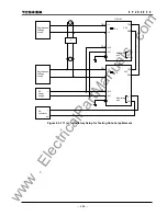
As the fault locator requires local and remote terminal currents, the fault locator can be tested
under the end-to-end synchronized test setup.
In the tests, a dynamic test set with the three-phase voltage and current source is required for
each terminal to simulate power system pre-fault, fault and post-fault conditions.
www
. ElectricalPartManuals
. com
Summary of Contents for GRL100-701B
Page 329: ... 328 6 F 2 S 0 8 5 0 w w w E l e c t r i c a l P a r t M a n u a l s c o m ...
Page 339: ... 338 6 F 2 S 0 8 5 0 w w w E l e c t r i c a l P a r t M a n u a l s c o m ...
Page 351: ... 350 6 F 2 S 0 8 5 0 w w w E l e c t r i c a l P a r t M a n u a l s c o m ...
Page 381: ... 380 6 F 2 S 0 8 5 0 w w w E l e c t r i c a l P a r t M a n u a l s c o m ...
Page 413: ... 412 6 F 2 S 0 8 5 0 w w w E l e c t r i c a l P a r t M a n u a l s c o m ...
Page 417: ... 416 6 F 2 S 0 8 5 0 w w w E l e c t r i c a l P a r t M a n u a l s c o m ...
Page 453: ... 452 6 F 2 S 0 8 5 0 w w w E l e c t r i c a l P a r t M a n u a l s c o m ...
Page 457: ... 456 6 F 2 S 0 8 5 0 w w w E l e c t r i c a l P a r t M a n u a l s c o m ...
Page 473: ...w w w E l e c t r i c a l P a r t M a n u a l s c o m ...

