130
6
F
2
S
0
8
5
0
Element Range
Step Default Remarks
TS2R
5.0 – 300.0s
0.1s
30.0s
Second shot reset time
TS3R
5.0 – 300.0s
0.1s
30.0s
Third shot reset time
TS4R
5.0 – 300.0s
0.1s
30.0s
Fourth shot reset time
TSUC
0.1 – 10.0s
0.1s
3.0s
Autoreclose success check time
[ARC – M]
Disabled/SPAR/TPAR/
SPAR & TPAR/MPAR2/MPAR3/
EXT1P/EXT3P/EXTMP
SPAR & TPAR Autoreclose mode
[ARCDIFG]
OFF/ON
OFF
High-resistance fault autoreclose
[ARC-BU]
OFF/ON
OFF
Backup trip autoreclose
[ARC-EXT] OFF/ON
OFF
External
start
[ARC – SM]
OFF/S2/S3/S4
OFF
Multi – shot autoreclose mode
[ARC-SUC]
OFF/ON
OFF
Autoreclose success checking
[MA-NOLK]
FT/T/S+T
FT
Control under NON-LINK in MPAR
[VCHK]
OFF/LB/DB/SYN
LB
Energizing direction
[VTPHSEL]
A/B/C
A
Phase of reference voltage
[VT – RATE]
PH/G / PH/PH
PH/G
VT rating
[3PH – VT]
BUS/LINE
LINE
Location of three – phase VTs
[UARCSW] P1/P2/P3
(P1)(
∗
)
User ARC switch for PLC
(
∗
)
If this switch is not used for PLC setting, it is invalid.
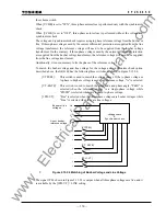
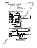
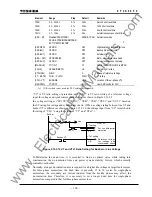
“VT” is VT ratio setting of protection, and “VTs1” is VT ratio setting of a reference voltage
input for voltage and synchronism check element as shown in Figure 2.16.9.1.
In a voltage setting, set “SY1UV”, “SY1OV”, “OVB”, “UVB”, “OVL1” and “UVL1” based on
the VT rating for voltage and synchronism check. (When a voltage rating between line VT and
busbar VT is different as shown in Figure 2.15.2.10, the voltage input from “VT” is matched to
the rating of “VTs1” using the setting of “VT” and “VTs1”.)
CB
Line VT
Busbar VT
VT setting
GRL100
Busbar
Line
VL
X
VTs1 setting
VB
Reference voltage
for voltage and
synchronism check
For line differential
protection
Figure 2.15.2.10 VT and VTs1 Ratio Setting for Busbar or Line Voltage
To determine the dead time, it is essential to find an optimal value while taking into
consideration the de-ionization time and power system stability factors, which normally
contradict each other.
Normally, a longer de-ionization time is required for a higher line voltage or larger fault current.
For three-phase autoreclose, the dead time is generally 15 to 30 cycles. In single-phase
autoreclose, the secondary arc current induced from the healthy phases may affect the
de-ionization time. Therefore, it is necessary to set a longer dead time for single-phase
autoreclose compared to that for three-phase autoreclose.
www
. ElectricalPartManuals
. com
Summary of Contents for GRL100-701B
Page 329: ... 328 6 F 2 S 0 8 5 0 w w w E l e c t r i c a l P a r t M a n u a l s c o m ...
Page 339: ... 338 6 F 2 S 0 8 5 0 w w w E l e c t r i c a l P a r t M a n u a l s c o m ...
Page 351: ... 350 6 F 2 S 0 8 5 0 w w w E l e c t r i c a l P a r t M a n u a l s c o m ...
Page 381: ... 380 6 F 2 S 0 8 5 0 w w w E l e c t r i c a l P a r t M a n u a l s c o m ...
Page 413: ... 412 6 F 2 S 0 8 5 0 w w w E l e c t r i c a l P a r t M a n u a l s c o m ...
Page 417: ... 416 6 F 2 S 0 8 5 0 w w w E l e c t r i c a l P a r t M a n u a l s c o m ...
Page 453: ... 452 6 F 2 S 0 8 5 0 w w w E l e c t r i c a l P a r t M a n u a l s c o m ...
Page 457: ... 456 6 F 2 S 0 8 5 0 w w w E l e c t r i c a l P a r t M a n u a l s c o m ...
Page 473: ...w w w E l e c t r i c a l P a r t M a n u a l s c o m ...

