200
6
F
2
S
0
8
5
0
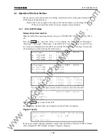
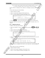
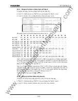
4.2.4.2 Displaying the Status of Binary Inputs and Outputs
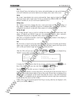
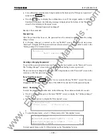
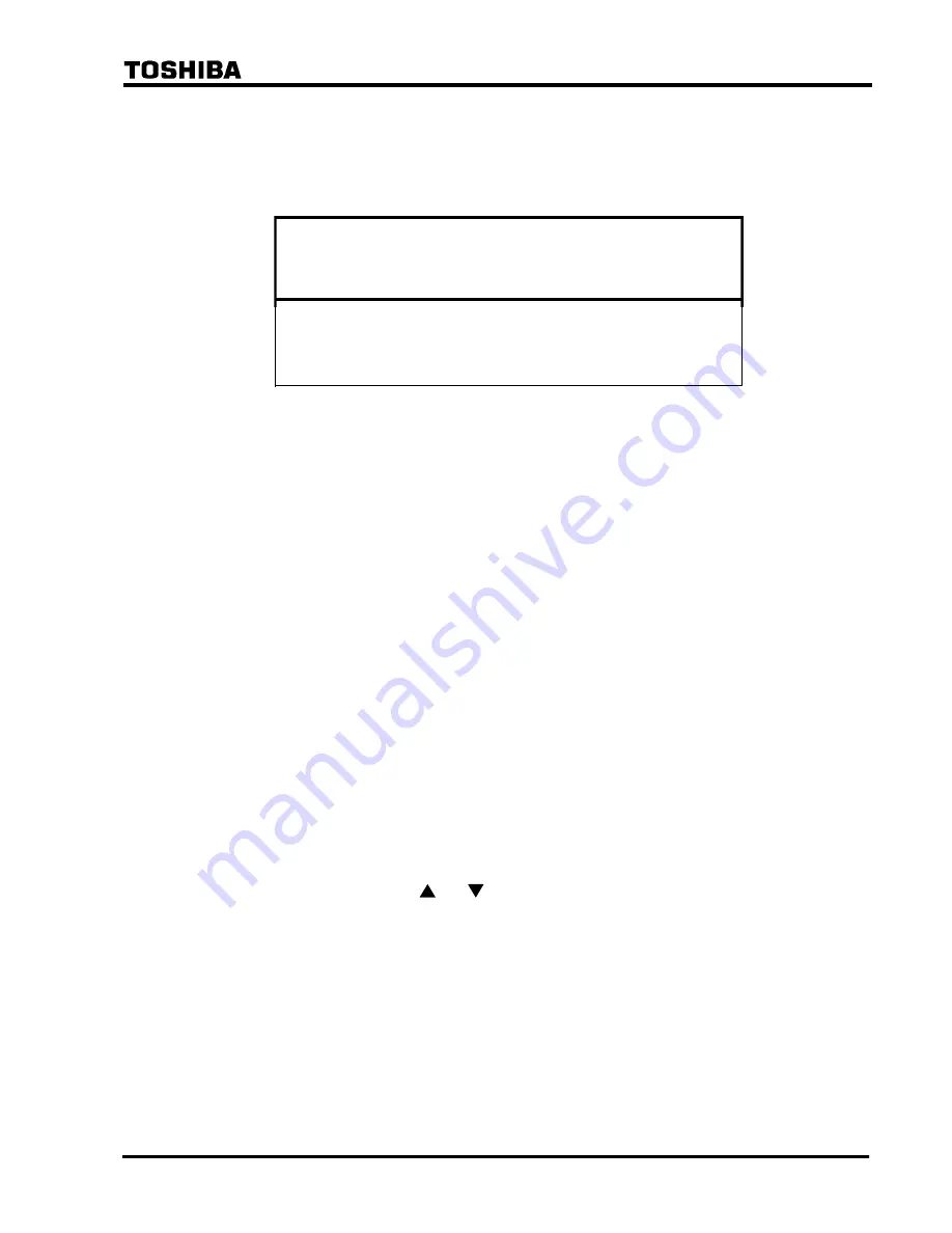
To display the binary input and output status, do the following:
•
Select 2 (=Status) on the top "MENU" screen to display the "Status" screen.
•
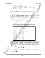
Select 2 (=Binary I/O) to display the binary input and output status.
/ 2 B i n a r y i n p u t
&
o u t p u t
3 / 8
I n p u t ( I
O
# 1
[ 0 0 0
0 0 0
0 0 0
0 0 0 0 0 0 ]
I n p u t
( I
O
# 2
[ 0 0 0
]
O u t p u t ( I
O
1 - t r i p )
[ 0 0 0
0 0 0
]
O u t p u t ( I
O
# 3
[ 0 0 0
0 0 0
0 0 0
0
]
O u t p u t ( I
O
# 4
[ 0 0 0
0 0 0
0 0 0
0 0 0
0 0
]
)
)
O u t p u t ( I
O
# 2
[ 0 0 0
0 0 0
0 0 0
0 0 0
0 0
]
I n p u t
( I
O
# 3
[ 0 0 0
0 0 0
0 0 0
0
]
)
)
)
)
#
I n p u t
( I
O
# 4
[ 0 0 0
]
)
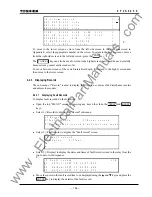
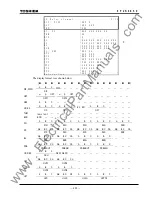
The display format of IO and FD modules is shown below.
[
]
Input
(IO#1)
BI1 BI2 BI3 BI4 BI5 BI6 BI7 BI8 BI9 BI10 BI11 BI12 BI13 BI14 BI15
Input
(IO#2) BI16
BI17
BI18 — — — — — — — — — — — —
Input
(IO#3:IO5) BI19 BI20 BI21 BI22 BI23 BI24 BI25 BI26 BI27 BI28 — — — — —
Input
(IO#3:IO6) BI19
BI20
BI21
BI22
BI23
BI24
BI25 — — — — — — — —
Input
(IO#4:IO4) BI34
BI35
BI36 — — — — — — — — — — — —
Output
(IO#1-trip)
TPA1
TPB1
TPC1
TPA2
TPB2
TPC2
— — — — — — — — —
Output
(IO#2)
BO1 BO2 BO3 BO4 BO5 BO6 BO7 BO8 BO9 BO10 BO11 BO12 FAIL BO13 —
Output
(IO#3:IO3) BO1 BO2 BO3 BO4 BO5 BO6 BO7 BO8 BO9 BO10 — — — — —
Output
(IO#3:IO5) BO1 BO2 BO3 BO4 BO5 BO6 BO7 BO8 BO9 BO10 — — — — —
Output
(IO#3:IO6)
BO1
BO2
BO3
BO4
BO5
BO6 — — — — — — — — —
Output
(IO#4:IO4) BO1 BO2 BO3 BO4 BO5 BO6 BO7 BO8 BO9 BO10 BO11 BO12 BO13 BO14 —
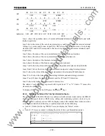
Lines 1 and 2 show the binary input status. BI1 to BI18 correspond to each binary input signal.
For details of the binary input signals, see Appendix G. The status is expressed with logical level
"1" or "0" at the photo-coupler output circuit. The module names of IO#1 to IO#4 in the table
depend on the model. (Refer to Appendix G.)
Lines 5 to 12 show the binary output status. TPA1 to TPC2 of line 5 correspond to the tripping
command outputs. Other outputs expressed with BO1 to BO14 are configurable. The status of
these outputs is expressed with logical level "1" or "0" at the input circuit of the output relay
driver. That is, the output relay is energized when the status is "1".
To display all the lines, press the and keys.
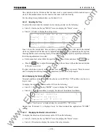
4.2.4.3 Displaying the Status of Measuring Elements
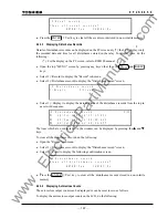
To display the status of measuring elements on the LCD, do the following:
•
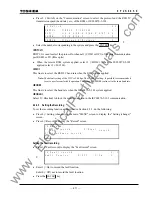
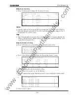
Select 2 (=Status) on the top "MENU" screen to display the "Status" screen.
•
Select 3 (=Relay element) to display the status of the relay elements.
www
. ElectricalPartManuals
. com
Summary of Contents for GRL100-701B
Page 329: ... 328 6 F 2 S 0 8 5 0 w w w E l e c t r i c a l P a r t M a n u a l s c o m ...
Page 339: ... 338 6 F 2 S 0 8 5 0 w w w E l e c t r i c a l P a r t M a n u a l s c o m ...
Page 351: ... 350 6 F 2 S 0 8 5 0 w w w E l e c t r i c a l P a r t M a n u a l s c o m ...
Page 381: ... 380 6 F 2 S 0 8 5 0 w w w E l e c t r i c a l P a r t M a n u a l s c o m ...
Page 413: ... 412 6 F 2 S 0 8 5 0 w w w E l e c t r i c a l P a r t M a n u a l s c o m ...
Page 417: ... 416 6 F 2 S 0 8 5 0 w w w E l e c t r i c a l P a r t M a n u a l s c o m ...
Page 453: ... 452 6 F 2 S 0 8 5 0 w w w E l e c t r i c a l P a r t M a n u a l s c o m ...
Page 457: ... 456 6 F 2 S 0 8 5 0 w w w E l e c t r i c a l P a r t M a n u a l s c o m ...
Page 473: ...w w w E l e c t r i c a l P a r t M a n u a l s c o m ...

