36
6
F
2
S
0
8
5
0
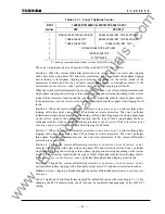
Element Range
Step
Default
Remarks
Communication
Mode
A
B
GPS
[SP.SYN] Master/Slave
Master(*3)
Sampling
synchronization
x x x
[CH. CON]
Normal/Exchange
Normal
Telecommunication port exchanger
x
x
x
[T.SFT1]
ON/OFF
OFF
Channel 1 bit shifting for multiplexer
x
x
x
[T.SFT2]
ON/OFF
OFF
Channel 2 bit shifting for multiplexer
x
x
x
[B.SYN1]
ON/OFF
ON
Channel 1 bit synchronising for
multiplexer
x x x
[B.SYN2]
ON/OFF
ON
Channel 2 bit synchronising for
multiplexer
x x x
[LSSV]
ON/OFF
OFF
Disconnector contacts discrepancy
check
x x x
[GPSBAK] OFF/ON
ON
Backup
synchronization
-- -- x
[AUTO2B](*6) OFF/ON
OFF
Automatic mode change
--
--
x
[SRC
θ
](*5)
Disable / I
I
Sampling timing deviation monitoring
with current
-- -- x
[IDSV] OFF/ALM&BLK/ALM
OFF
Id
monitoring
x
x
x
[RYIDSV]
OFF/ON
ON
Relay address monitoring
--
x
x
(*1) Current values shown in parentheses are in the case of 1A rating. Other current values are in the
case of 5A rating.
(*2) This setting is valid for three-terminal application models of the GRL100.
(*3) In the actual setting, one terminal is set to "Master" and other terminal(s) to "Slave".
(*4) OCCHK, [SRC
θ
] and HYS
θ
are enabled by setting the [TERM] to "2TERM".
(*5) [AUTO2B] is enabled by setting the [TERM] to "2TERM" and [SRC
θ
] to "I".
(*6) This setting is only used when there is a fixed difference between the sending and receiving
transmission delay time. When the delay times are equal, the default setting of 0
µ
s must be
used.
(*7) If the channel delay time of CH1 or CH2 exceeds the TDSV setting, then the alarm "Td1 over"
or "Td2 over" is given respectively.
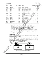
CT Ratio matching
When the CT ratio is different between the local terminal and the remote terminal(s), the CT
ratio matching can be done as follows:
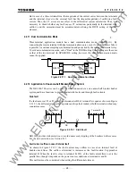
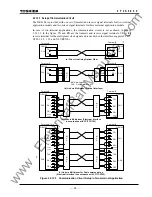
The differential element settings are respectively set to the setting values so that the primary fault
detecting current is the same value at all terminals. Figure 2.2.14.1 shows an example of CT ratio
matching. The settings for DIFI2, DIFGI, DIFSV and DIFIC should also be set with relation to
the primary current in the same manner of the DIFI1 setting.
CT ratio : 2000/1A
Terminal-A
Terminal-B
GRL100
GRL100
DIFI1=800A / CT ratio(2000/1A)
= 0.4A
CT ratio : 4000/1A
DIFI1=800A / CT ratio(4000/1A)
= 0.2A
Primary sensitivity = 800A
Figure 2.2.14.1 Example of CT Ratio Matching
www
. ElectricalPartManuals
. com
Summary of Contents for GRL100-701B
Page 329: ... 328 6 F 2 S 0 8 5 0 w w w E l e c t r i c a l P a r t M a n u a l s c o m ...
Page 339: ... 338 6 F 2 S 0 8 5 0 w w w E l e c t r i c a l P a r t M a n u a l s c o m ...
Page 351: ... 350 6 F 2 S 0 8 5 0 w w w E l e c t r i c a l P a r t M a n u a l s c o m ...
Page 381: ... 380 6 F 2 S 0 8 5 0 w w w E l e c t r i c a l P a r t M a n u a l s c o m ...
Page 413: ... 412 6 F 2 S 0 8 5 0 w w w E l e c t r i c a l P a r t M a n u a l s c o m ...
Page 417: ... 416 6 F 2 S 0 8 5 0 w w w E l e c t r i c a l P a r t M a n u a l s c o m ...
Page 453: ... 452 6 F 2 S 0 8 5 0 w w w E l e c t r i c a l P a r t M a n u a l s c o m ...
Page 457: ... 456 6 F 2 S 0 8 5 0 w w w E l e c t r i c a l P a r t M a n u a l s c o m ...
Page 473: ...w w w E l e c t r i c a l P a r t M a n u a l s c o m ...


