Chapter 2 Power Supply and Computer Installation
1.
Don’t
connect any cables to your radio yet!
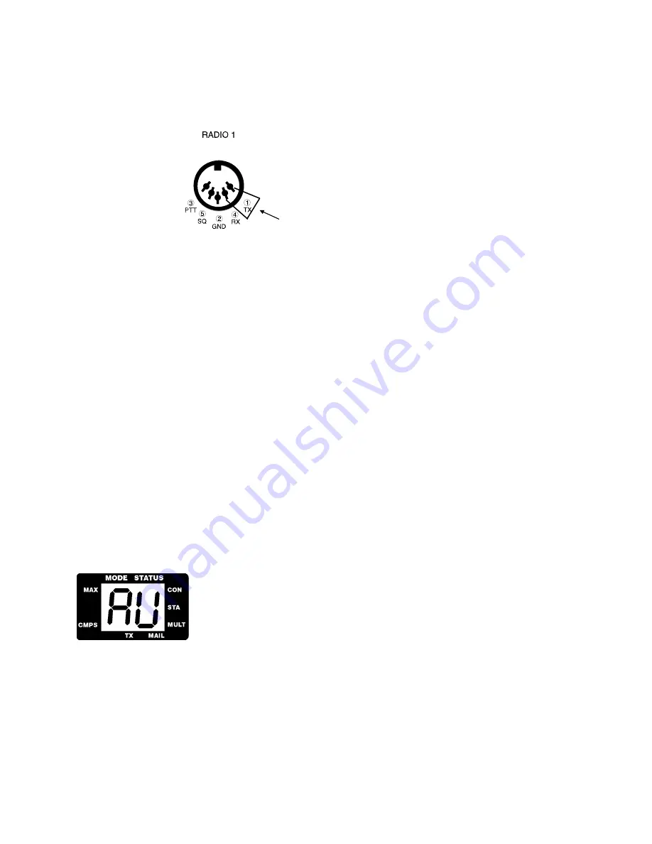
2. If a loop-back jumper is included with your shipment of the DSP-232, plug one end into the 1 hole (TX)
and the other end into the 4 hole (RX) of Radio 1 port on the back of the DSP-232, and go to step 7. If you
did not receive a loop-back jumper, continue following the steps.
Insert Loop-back jumper in holes 1 and 4
3. Remove one of the 5-wire, shielded radio cables from the DSP accessory bag. If you have a single 10-Ft.
cable with 5-pin connectors on each end, cut the cable to the length you need to reach your primary radio.
4. With your pocket knife or wire strippers, remove about an inch (2.5 cm) of cable jacket exposing the five
colored wires and the shield-wire, being careful not to accidentally nick the wires’ insulation.
5. Strip about 1/4 inch (7 mm) of insulation from the green and white wires and short them together by
twisting gently twisting their ends together.
6. Plug the cable into the 5-pin RADIO-1 socket on the DSP’s rear panel. Make sure that the cable at the
connector end faces downward as it leads away from the controller.
7. Set the RADIO 1 AFSK LEVEL pot on the rear of the DSP to 50% rotation (straight up and down) using a
small screwdriver.
8. Turn on your computer. Load and run your communications program. (Choose the TTY option, if
available.)
If you’re using an AEA program, follow its manual’s instructions to enter the packet mode, then skip to Step 11.
Note
: Early version of PC PakRatt for Windows 2.0 do not list the DSP-232 in the TNC menu. To operate
your DSP-232, you will select the DSP-1232 from the TNC menu. To PC PakRatt for Windows, your
DSP-232 ‘looks’ just like a DSP-1232. Later versions of PC PakRatt for Windows have the DSP-232 listed
in the TNC menu. THIS IS THE ONLY DIFFERENCE BETWEEN EARLY AND LATE RELEASES
OF PC PAKRATT FOR WINDOWS version 2.0.
Note
: You may use a wide range of terminal baud rates with the DSP, but we recommend 1200 baud now
to keep this procedure easy and consistent.
9. Press the DSP’s power switch to the ON position.
The seven segment LCD symbols ‘AU’ (AU stands for Auto Buad) will light. (If the
above doesn’t happen, then refer to
Chapter 13 - Troubleshooting
.
If your serial port is operating at 1200 baud (this is the terminal baud rate), 7-bit even parity as recommended, you’ll
see the following message:
Please type a star
(
*
)
for autobaud routine.
If your serial port is operating at 2400, 4800, 9600, or 19,200 baud (this is terminal baud), you may see some
“garbage” characters. This is normal and you should proceed with Step 10.
2-6
September, 05
Summary of Contents for DSP-232
Page 120: ...Chapter 6 GPS Applications September 05 6 1...
Page 138: ...Chapter 7 Maildrop Operation 7 18 September 05...
Page 158: ......
Page 159: ...Chapter 8 ASCII and Baudot Operation September 05 8 1...
Page 185: ......
Page 186: ...Chapter 9 AMTOR Operation September 05 9 1...
Page 198: ......
Page 199: ...Chapter 10 Morse Operation September 05 10 1...
Page 207: ......
Page 208: ...Chapter 11 SIAM and NAVTEX Operation September 05 11 1...
Page 230: ......
Page 231: ...Chapter 12 PACTOR Operation September 05 12 1...
Page 240: ...Chapter 13 Troubleshooting September 05 13 9...
Page 254: ...Chapter 13 Troubleshooting 13 9...
Page 256: ...DSP 232 Manual Addendum September 05 AD 2...
Page 259: ...Appendix A Radio Connections Radio Connection Diagrams September 05 A 3...
Page 260: ...Appendix A Radio Connections A 4 September 05...
Page 261: ...Appendix A Radio Connections September 05 A 5...
Page 262: ...Appendix A Radio Connections A 6 September 05...
Page 263: ...Appendix A Radio Connections September 05 A 7...
Page 267: ...Appendix D Mailbox Upgrade September 05 D 2...
Page 268: ...Appendix E Schematics and Pictorial September 05 E 3...


