Analog Peak Current Mode
190
SNIU028A – February 2016 – Revised April 2016
Copyright © 2016, Texas Instruments Incorporated
Loop Mux
5.12 Analog Peak Current Mode
In the Loop Mux, there are two simple registers – PCMCTRL and APCMCTRL.
PCMCTRL has only one bitfield:
•
PCM_FILTER_SEL. This field selects a filter output. The filter output is used for the start of the
compensating ramp.
ADPCMCTRL has 3 bitfields:
•
PCM_FE_SEL – selects which Front End is used to compare the compensation ramp to the power
supply current
•
PCM_LATCH_EN – enables the latching of the peak current detection to the end of the PCM frame
•
PCM_EN – enables peak current mode
Refer to the reference firmware code provided with UCD3138PSFBEVM-027 and TI application note for
Phase Shift Full Bridge peak current mode control implementation with UCD3138.
5.13 Automatic Cycle Adjustment
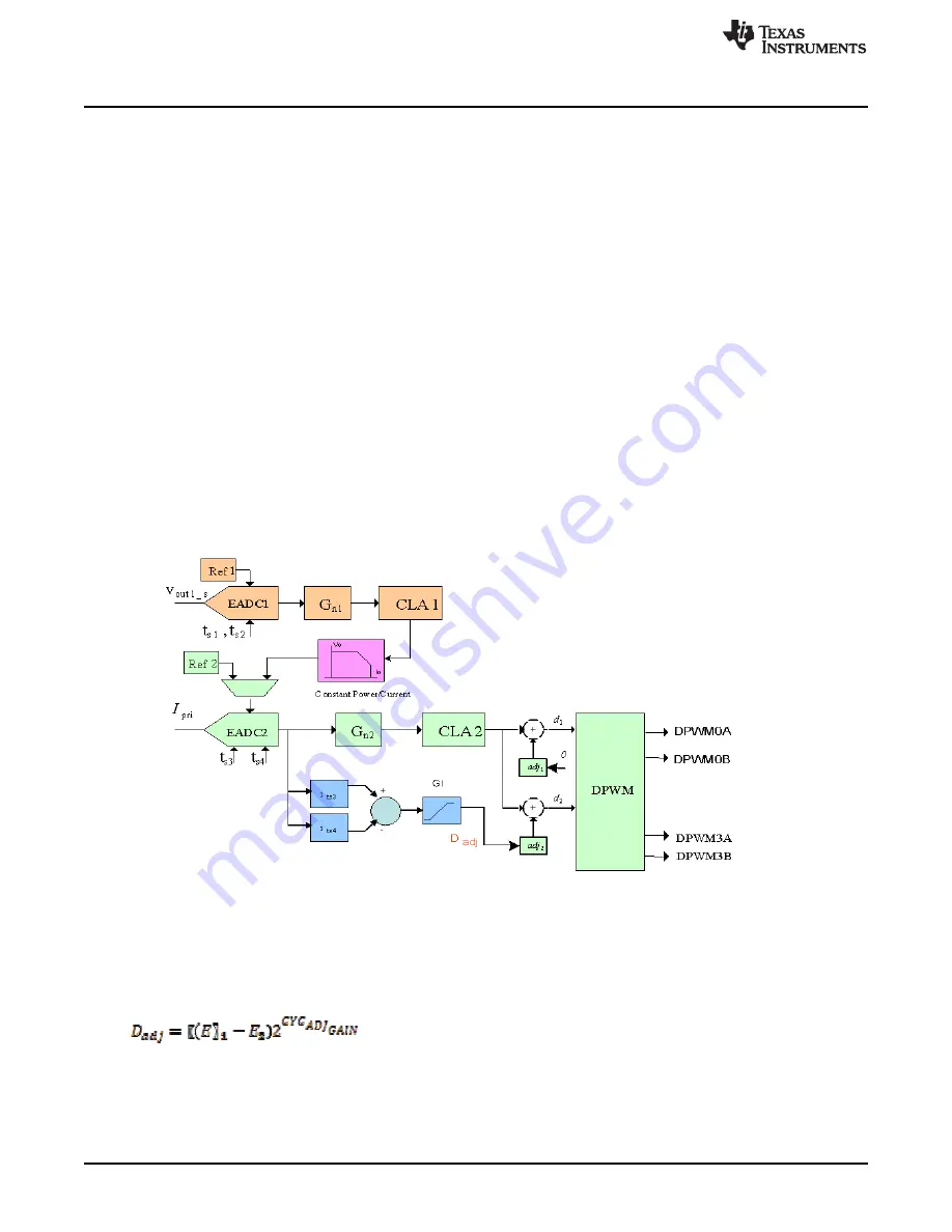
The Loop Mux contains registers which control and monitor automatic cycle adjustment. It can be used to
balance current between two legs of a parallel topology, such as a multiphase PFC. It can also be used
for flux balancing in bridge topologies.
illustrates an example of it being used in a bridge
topology. The cycle adjustment is shown on the bottom left hand side, connecting the output of EADC2 to
D
adj
. Current is being measured on each half cycle, so the two samples come from the same EADC. The
output is being used to adjust DPWM3 Duty to maintain flux balance.
Figure 5-1. UCD3138 Flux Balancing Approach
5.13.1 Calculation
The output of this logic is a cycle adjustment number provided to the DPWM based on the difference
between two samples from one or two front end EADCs. The equation is:
where
•
D
adj
= Duty Cycle Adjust
•
E
1
E
2
= EADC error values(
i
ts2
and
i
ts4
) shown in the figure CYC_ADJ_GAIN = bitfield value in CYCADJCTRL
register
(2)


