99
100
101
102
0
1
2
3
4
5
6
7
8
9
10
11
12
13
14
15
Dither Counter
D
A
C
v
a
lu
e
Front End DAC
118
SNIU028A – February 2016 – Revised April 2016
Copyright © 2016, Texas Instruments Incorporated
Front End
3.2
Front End DAC
The reference voltage for the Front End is set by the DAC, sometimes called the EADC DAC. This is a 10
bit analog to digital converter, with a nominal step size of 1.5625 millivolts per bit. The DAC input is a
unsigned 10 bit number, giving a range from 0 to 1.6 Volts.
In the simplest configuration, the DAC is set by writing to the EADCDAC register:
FeCtrl0Regs.EADCDAC.bit.DAC_VALUE = 100 * 16;//set 10 bit DAC to 100 (.15625 Volts)
The 16X multiply is necessary because the DAC logic also supports a 4 bit dither capability.
The DAC_VALUE bit has 14 total bits - 10 actual DAC bits, and 4 bits that are used for dither:
Figure 3-5.
13
12
11
10
9
8
7
6
5
4
3
2
1
0
DAC Value
Dither
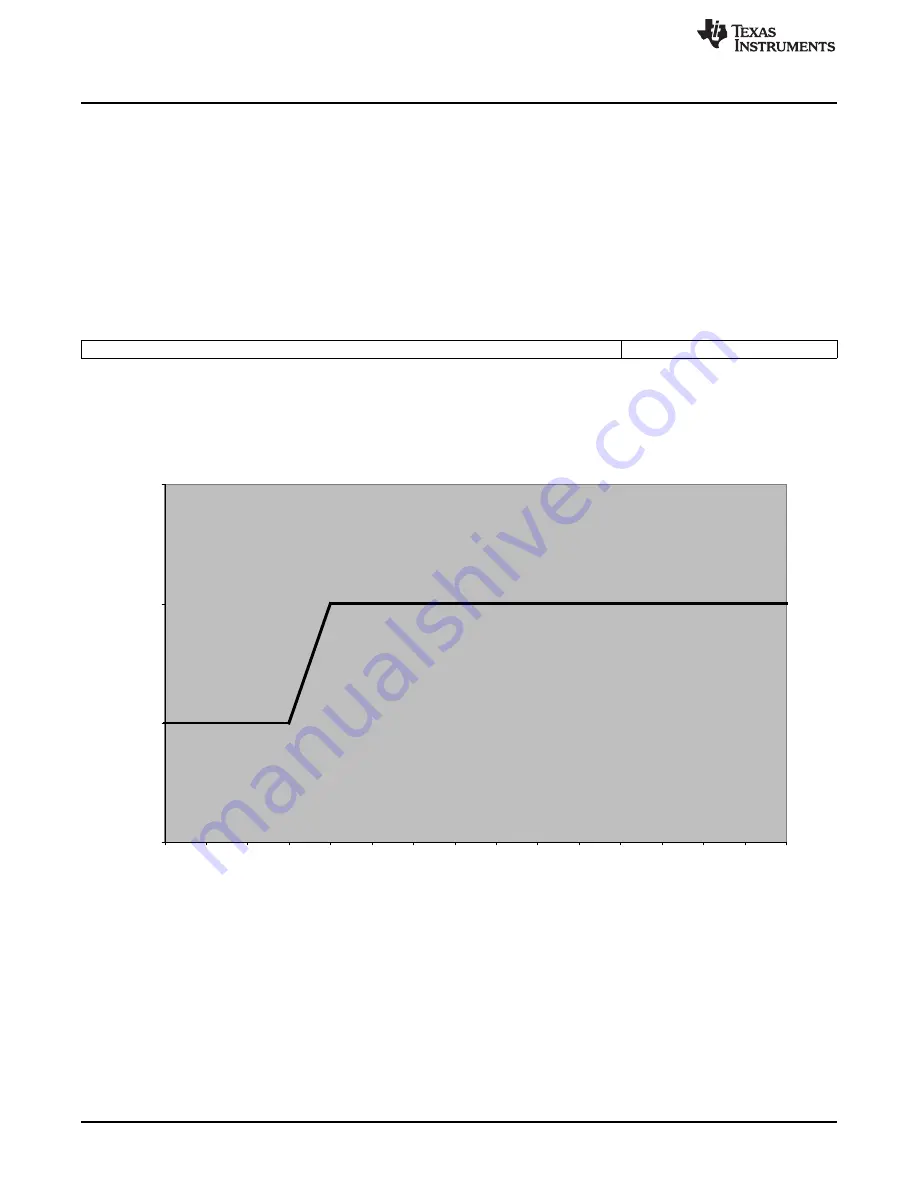
This dither has a 4 bit counter driven by a selected DWPM signal, which will switch back and forth
between 2 DAC values. For example, if the DAC value is set to 100.75 *16, there will be a 0b11000100
(equivalent to 100) in the 10 DAC bits, and a 0b1100 (equivalent to 12 or 0.75 x 16) in the 4 dither bits.
The dither logic will put out a 100 for 4 counts and 101 for 12 counts. This will give an average of 100.75.
Here is the waveform:
Figure 3-6. DAC Dither
The dither counter will increment at the start of a pulse on DPWMA and/or DPWMB. The specific DPWM
pins used are selected in the FECTRLxMUX registers in the Loop Mux.
For example, to set the rising edge of DPWM3B to trigger DAC dither on Front End 2:
LoopMuxRegs.FECTRL2MUX.bit.DPWM3_B_TRIG_EN = 1;
//set DPWM3B up to trigger dither.
Note that if the DPWM pin is not active, because of anything from a zero filter output to a fault, the dither
counter will not be incremented.
To enable dither, the DAC_DITHER_EN bit must be set:
FeCtrl0Regs.EADCDAC.bit.DAC_VALUE = (int)(100.25 * 16);


