4
ArbConnection
Generating Waveforms Using the Equation Editor
4-63
Now that we somewhat understand the terms we use for the pulse
design, we start with an example how to design the pulse train as
shown in Figure 4-47. If you already have some pulses shown on
your pulse composer screen, click on New to start from a fresh
page. Another step before you design your pulse train is to set the
design parameters in the options menu that will determine the way
that the pulse will be distributed in your waveform memory. Click on
View
→
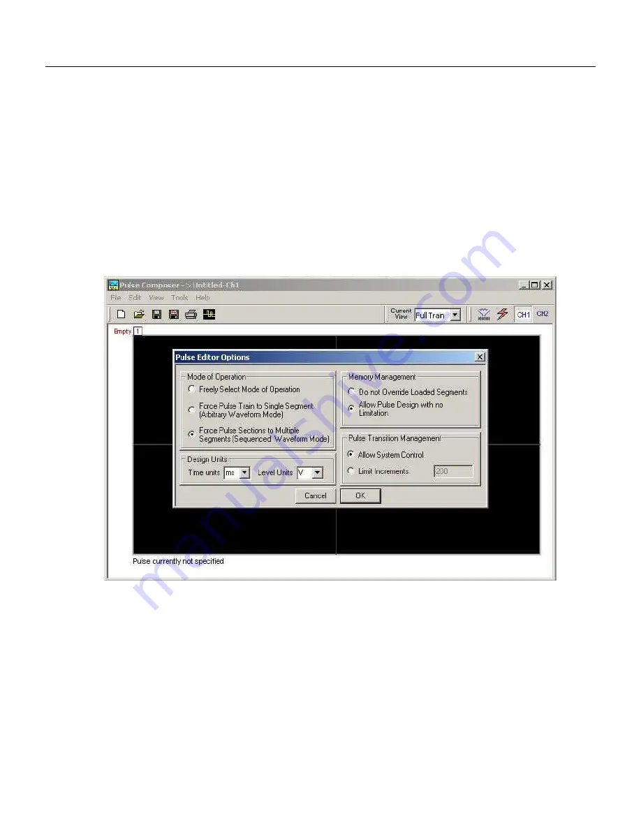
Options and refer to Figure 4-49 throughout the following
description.
Figure
4-49, Selecting Pulse Editor Options
Setting the Pulse Editor
Options
As shown in Figure 4-49, the pulse editor option dialog box is
divided to functional groups: Mode of operation, Design Units,
Memory Management and Pulse Transition Management. These
groups are described below.
Mode of Operation
There are three options in the mode of operation group.
The force pulse train to single segment option is recommended if
you are using one pulse section only. In this case, the pulse
waveform will occupy one segment only and the generator will
automatically be set to operate in arbitrary mode.
Summary of Contents for 5064
Page 26: ...1 5 Figure 1 2 ArbConnection The Control Panels Figure 1 3 ArbConnection The Wave Composer...
Page 71: ...2074 User Manual 2 18 This page intentionally left blank...
Page 145: ...2074 User Manual 3 74 Figure 3 48 Reading the 2074 Internal Temperature...
Page 220: ...4 ArbConnection Logging SCPI Commands 4 75 Figure 4 58 Log File Example...
Page 221: ...2074 User Manual 4 76 This page was intentionally left blank...
Page 333: ...2074 User Manual 7 2...
Page 359: ...2074 User Manual 7 28 This page was intentionally left blank...
Page 360: ...Appendices Appendix Title Page A Specifications A 1 1...
Page 361: ...2074 User Manual 2...


