background image

Super Systems Inc.                     


 Page 50 of 107 


Color Touch Screen Data Logger Operations Manual 

the “Survey Results (Pass/Fail)” field is for the results of the survey.  The “Notes” field is for any 

general notes for the report. 

Manually Creating a Survey Record 

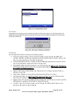
Clicking on the “Advanced: Manually Create Survey Record” link from the Load Survey Data 

screen will allow the user to create a survey record to use.  Clicking on this link will display the 

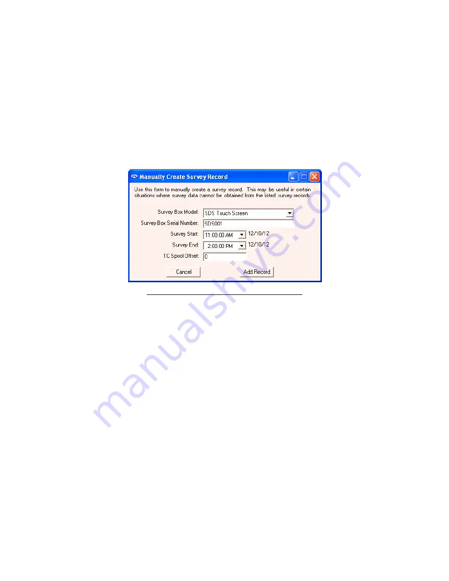
“Manually Create Survey Record” form (Figure 60).  Five pieces of data are required to manually 

create a record: the SDS model, serial number, the start time and date of the survey, the end 

time and date of the survey, and the TC Spool Offset. All data will need to be downloaded from 

the SDS either before or after this process in order to get data.  To download all data, please 

refer to section 

SDS 

 Download Surveys and Data


Figure 60 - Manually Create Survey Record form


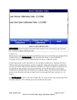
The drop-down list next to “Survey Box Model” contains a list of the available models. Make 

sure to select the appropriate Color SDS Data Logger. Select the model type (the Color SDS 

Data Logger is referred to as “SDS Touch Screen”). Enter the SDS serial number on the next 

line, “Survey Box Serial Number”.  The serial number can be found in the About window, as 

discussed in the About section.  The process for selecting the start date/time and the end 

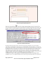
date/time is the same.  To select a date, click on the down arrow next to the time listed.  This 

will bring up a calendar from which the user can select a new date (Figure 61).  Select the new 

date by clicking on it. 

Summary of Contents for SDS8120

Page 1: ...COLOR TOUCH SCREEN DATA LOGGER OPERATIONS MANUAL Super Systems Inc 7205 Edington Drive Cincinnati OH 45249 513 772 0060 800 666 4330 Fax 513 772 9466 www supersystems com...

Page 2: ...ate Sutton Coldfield West Midlands B75 7BU UNITED KINGDOM Phone 44 0 121 329 2627 http www supersystemseurope com Super Systems Mexico Sistemas Superiores Integrales S de RL de CV Quer taro QRO CP MEX...

Page 3: ...12 Voltage connections 12 4 20 mA Current Loop connections 12 Survey Templates 12 Installing the SDS Software 14 Connecting the SDS Data Logger to a Network 16 In Windows Vista and Windows 7 17 In Win...

Page 4: ...ison Check 59 File Save File Save As Save Button 62 File Export 62 File Print 62 Print Button 64 File Print Preview 65 File Exit 65 SDS Menu Options 65 SDS Manage Survey Templates 65 SDS Download Surv...

Page 5: ...ndix 1 Quick Start Guide 95 Unpacking the Color SDS Data Logger 95 Warming Up and Charging the Data Logger 96 Turning on the Data Logger 97 Connecting the Thermocouple Wires and Setting the Input Type...

Page 6: ...tools needed to generate uniformity reports The Report Manager includes a report writer that allows the user to set up reports to meet their specific requirements The Template Manager allows survey sp...

Page 7: ...requires SDS firmware level 1 10 or later Software Installation You will find the SDS Reporter software CD that ships with the unit includes all the reporting and administrative utilities Insert the...

Page 8: ...gger A possible example of this could be Connecting the SDS Data Logger to a Network Less frequently it may be necessary to change the IP address of the data logger or to change it from a dynamic IP a...

Page 9: ...91181 An Ethernet Driver settings window will appear giving you the ability to specify an IP address To do so click the Specify an IP address radio button see Figure 6 Then enter an IP address manuall...

Page 10: ...e performed at different temperatures and printed with the certificate Setting the DIP switches to Assign Board Numbers Each input board must have a unique address assigned by the DIP switches on each...

Page 11: ...ager will be the selected channels for the survey It is strongly suggested that you select a template prior to running a survey If you want to create new templates please see the section SDS Template...

Page 12: ...Volts can be directly connected to the terminal blocks When measuring ground referenced voltages all references must share a common ground reference If the voltage sources are connected to different...

Page 13: ...can view the input channel data on a number of different screens The overview display will display all channels on the device At any time the operator can view the data in real time from the computer...

Page 14: ...given the Report dialog to generate a survey report Reports use logged data and the user specified interval in the report The report template that is selected will form the final report view with all...

Page 15: ...r the installer Clicking the Next button will continue with the installation process Figure 12 Figure 12 Installation ready screen Clicking on the Cancel button will prompt the user to confirm exiting...

Page 16: ...ports If you are connecting the data logger to your network you will need an Ethernet cable the cable provided is a crossover cable for direct connections to a PC The cable is plugged into the data lo...

Page 17: ...ough the Control Panel in Microsoft Windows Using the crossover cable will require the Local Area Connection to be modified In Windows Vista and Windows 7 In Windows Vista and Windows 7 open the Netwo...

Page 18: ...refer to the computer manual Figure 17 Changing IP address settings In Windows XP The Properties can be changed by highlighting the connection and using the right mouse button to click and select the...

Page 19: ...r Windows 7 the software is called Mobile Device Center If the required software was not installed prior to installing SDSReporter the SDSReporter Setup utility run from setup exe would have installed...

Page 20: ...the drivers but close the device setup window from ActiveSync or Mobile Device Center NOTE If there is any question as to whether the computer is detecting the data logger and connecting to it proper...

Page 21: ...to obtain it from the Instrument Information window as shown in Figure 24 Figure 24 Instrument Information screen and IP address Once you ve entered the needed web address you will see a screen that l...

Page 22: ...mation about the unit The viewable Menu items change depending on the login value The complete list of Menu items includes User Level Access or Higher Required Survey Instrument Information Chart Scal...

Page 23: ...vey The appropriate template can be chosen from the dropdown menu in the top right hand corner The Edit Template button allows for changes to be made to the selected survey When editing a survey press...

Page 24: ...Super Systems Inc Page 24 of 107 Color Touch Screen Data Logger Operations Manual has been selected and any necessary edits have been made press Start Survey to begin Figure 28 Survey Window...

Page 25: ...07 Color Touch Screen Data Logger Operations Manual Instrument Information Figure 29 Instrument Information Instrument Information displays the condition of several parameters for the SDS and no chang...

Page 26: ...g Window Chart scaling allows the user to adjust the maximum and minimum degrees displayed on the chart To change press the blue button with the max or min number press OK then press Save View Input T...

Page 27: ...ge 27 of 107 Color Touch Screen Data Logger Operations Manual Figure 31 View Input Types View Offsets View Offsets displays the offset values for each thermocouple channel on the SDS No changes can be...

Page 28: ...32 View Offsets Select Input Channels Select Input Channels allows the user to manually determine whether a thermocouple is included in a survey or not while the survey is running First press Select I...

Page 29: ...Super Systems Inc Page 29 of 107 Color Touch Screen Data Logger Operations Manual Figure 33 Select Input Channels Figure 34 Select Inputs...

Page 30: ...will be 1 and the Range End will be 20 Any interval in between can also be used Press Set Range Input Types to save Figure 35 Edit Input Types Edit Offsets The Edit Offsets option will change the off...

Page 31: ...ied First select the temperature type from the drop down menu then enter the spool correction value and press Set Spool Correction to save Press return to go back to the Menu list The thermocouple spo...

Page 32: ...107 Color Touch Screen Data Logger Operations Manual Figure 37 Set Spool Correction About This screen will display basic information about the SDS including the version and the serial number Nothing o...

Page 33: ...perature measured at each data logger terminal where the cold junction is created is correctly scaled Both types of calibration require a sourcing device and thermocouple wire The sourcing device shou...

Page 34: ...umbers represents each individual input A 20 input SDS Data Logger will feature four circuit boards depicted on this screen while a 40 input unit will feature eight circuit boards Since each board has...

Page 35: ...ation should be used instead of the regular cold junction thermistor calibration unless the cold junction temperatures are reading a temperature that is much too high for what the ambient temperature...

Page 36: ...r Systems Inc Technical Support at 800 666 4330 Datalog Deletion The Color SDS Data Logger includes an option to delete log data files and survey data files This option is useful when these data files...

Page 37: ...Logger Operations Manual Figure 43 Datalog Deletion Screen Passcodes This screen allows the user to set the passcodes to access the higher level functions on the SDS To change either passcode press t...

Page 38: ...ta log files starting with the oldest automatically as the storage card nears its full capacity it will not delete data log files that have been written less than 30 days before the current system dat...

Page 39: ...rd Compact Database When clicked Compact Database optimizes and reduces the size of the database contained on the storage card Read Write Data Using this feature you can view the raw data on the under...

Page 40: ...red in Figure 47 and internal thermistor Figure 47 Location of Ambient External Thermistor Figure 48 Configuration Menu IMPORTANT Before attempting to access Configuration features please contact Supe...

Page 41: ...default values A user may decide to use this feature if for example temperature readings from the SDS are deemed to be outside a certain acceptable range and subsequent calibrations are not successful...

Page 42: ...puts button The Select Inputs screen will appear Select each input for which you would like to reset the nominals and then press Select Highlighted for each one Note that you may enter a range of inpu...

Page 43: ...nimize the effect of outside temperature variations on thermocouple temperature readings It is possible to adjust K Factor settings from the Set K Factors menu but doing so is not recommended without...

Page 44: ...Logger Operations Manual Figure 52 Set K Factors SDX Control By selecting Run for SDX Control the SDS will run a program called SDX that monitors thermocouples to ensure they are calibrated properly u...

Page 45: ...ORTANT Avoid running SDX without first contacting Super Systems Inc Technical Support 800 666 4330 Modbus Control Running Modbus Control will enable the Modbus protocol to read and write registers To...

Page 46: ...Super Systems Inc Page 46 of 107 Color Touch Screen Data Logger Operations Manual Figure 54 Modbus Control Not Running Screen Figure 55 Run Modbus Control Window...

Page 47: ...ning for more details Figure 56 SDS Reporter initial screen When the SDS Reporter software is started up the user sees the above screen Figure 56 The four menu options to choose from are File SDS Opti...

Page 48: ...box The software will open the dialog box in the SDSReports folder typically C SSi SDS SDSReports for existing reports SDSReport to open The Report Properties tab contains several tabs which in turn c...

Page 49: ...the survey to use and click on the Use button Information included with the data sources is Template Name Company Name Furnace Id Survey box Serial number and the date time range of the survey data A...

Page 50: ...a will need to be downloaded from the SDS either before or after this process in order to get data To download all data please refer to section SDS Download Surveys and Data Figure 60 Manually Create...

Page 51: ...ayed to the user and the record will not be added Figure 62 Figure 62 Survey start end date error message Enter the TC spool offset and click on the Add Record button to add the record Clicking on the...

Page 52: ...ple settings and it also lists the active thermocouples The information in the thermocouple settings includes the temperature type F or C the number of thermocouples the number of TCs used in the repo...

Page 53: ...d provide an optional description for that TC Figure 67 Define Control TC screen Clicking on the Accept button will set the selected control TC s Once a control TC s has been selected the TC s number...

Page 54: ...he Thermocouples Tab will affect the TCs plotted on the Chart Tab The Thermocouples tab also includes an option to view and edit individual TC correction factors see Figure 69 Once these correction fa...

Page 55: ...typically the C SSi SDS folder The default passcode is 2 To change it open the SDSReporter ini file and add this line in the SETTINGS block of the ini file PASSCODE x Where x is zero or a positive int...

Page 56: ...to use The next tab is the Survey Box tab which contains information about the survey box itself such as the make and model the serial number whom the survey box was calibrated by and the calibration...

Page 57: ...Survey Details Tab The next tab is the Survey Parameters Tab Figure 73 The Survey Parameters tab contains the survey tolerance the survey setpoint the overtemp setpoint the simulated load in pounds a...

Page 58: ...Controller Settings area and this tab also contains the PID Settings cycle time dead band output limit PB Gain rate and reset Figure 74 Report Properties Controller Tab The User Defined tab contains t...

Page 59: ...s Manual Figure 75 User Defined Fields screen Comparison Check SDS Reporter includes two Comparison Check tabs as shown in Figure 76 The two Comparison Check tabs perform the same function with differ...

Page 60: ...ire Correction Thermocouples click View Offsets Used in Survey button Adjacent Instrument Correction Factor Thermocouples click View Offsets Used in Survey button Adjacent T C Temperature Readings for...

Page 61: ...e high and low temperature tolerance levels based on the setpoint This display will change based on the tolerance level and setpoint defined in the Report Parameters For more information about the fun...

Page 62: ...n this menu option is clicked the software will automatically begin to export the report selected to a word document Once the report has been exported the new document will be displayed Note no save d...

Page 63: ...The Print Approach TC Data menu option will allow the user to just print the approach data in a tabular format The Print All menu option will print all of the options Report Survey TC Data Approach T...

Page 64: ...following tags until another n tag is found Using the displayed screen as an example the following could be an excerpt from the template file 1 Survey 1 Duration SDS DUR 2 Survey 2 Duration SDS DUR 3...

Page 65: ...ay a print preview of the desired report Figure 83 Print Preview screen File Exit This menu option will exit the application SDS Menu Options SDS Manage Survey Templates The Manage Survey Templates me...

Page 66: ...DS devices found box Select the instrument from which to download the data files from the drop down list box labeled SDS Under the Options menu the Download menu option Figure 86 will allow the user t...

Page 67: ...see Figure 88 Note since there may a large number of files to download this process may take several minutes to complete When all of the files have been downloaded the words Operation Complete will b...

Page 68: ...lection box that will allow the user to choose which device to gather the real time data from If the Multiple SDS Mode menu option is not checked then the SDS software will gather real time data from...

Page 69: ...ng the y axis the refresh sets the range from 0 to 2400 For the minutes along the x axis the refresh encompasses approximately two hours Note when the Real time screen first loads up the graph encompa...

Page 70: ...an button or the Zoom button has been selected the user can still select or de select the TCs This will not affect the zoom status or the pan status The Override Tolerance checkbox will allow the user...

Page 71: ...rable consequences When the operator has selected the correct data logger he she can click on the Load button to load the survey data To select multiple sequential records hold down the Shift key and...

Page 72: ...SDS instrument through the SDS Reporter software is possible When the test has finished one of three options will happen 1 No SDS found No SDS instruments were found on the network Check the network...

Page 73: ...hat did respond successfully to the ping Figure 98 The most common cause is different subnets between the SDS and the computer Figure 99 The user may need to change the IP address of the SDS through m...

Page 74: ...ch for the application When checked this will display the Begin Survey label for the survey on the real time graph Figure 101 Figure 101 Label from real time graph Options Color Screen Scanning This i...

Page 75: ...ure 103 Figure 103 Automatic Update screen If no updates are available then the software will display a message box informing the user Figure 104 Figure 104 No updates message box Help About The About...

Page 76: ...from the data tags can be seen by opening the Example report from the SDS Reporter provided with the installation The only data not generated from data tags is the tabular print out of the actual tem...

Page 77: ...ce ID SDS FID SDS FM Furnace make model SDS FM SDS FT Furnace type SDS FT SDS FU Furnace use SDS FU SDS FD Furnace dimensions SDS FD SDS FC Furnace Class SDS FC SDS FOR Furnace operating range SDS FOR...

Page 78: ...DS SDSM SDS SDSS Survey box serial number SDS SDSS SDS SDSC Survey box calibrated by SDS SDSC SDS SDSCD Survey box calibration date SDS SDSCD SDS SDSCF Survey box correction factor SDS SDSCF SDS SPEC...

Page 79: ...osen SDS CTN Control thermocouple Inserts None if SDS CTN None is defined degree type SDS ED Survey end date SDS ED SDS ET Survey end time SDS ET SDS TCM Thermocouple map image SDS TCM SDS UD1 User de...

Page 80: ...isplay survey information for the multiple survey report feature See the section Print Multiple Surveys for more information on how to use these data tags Sample Output Tag Sample Output SDS FILE SDSR...

Page 81: ...6 SDS SDSM SSI SDS8120 SDS SDSS SDS60293201 SDS SDSC Super Systems Inc SDS SDSCD 1 15 12 SDS SDSCF 1 0 SDS SPEC AMS 2750 D and E SDS INT 10s SDS T F SDS SIM 500 SDS OVS None SDS MIC N A SDS RES Passed...

Page 82: ...00 AM SDS TCM Thermocouple image TC Offsets Tag Description Usage o1 Offset for TC1 o1 cf1 Individual correction factor for TC1 cf1 Tag Sample Output o1 1 Min Max Mean Spread Deviation Tag Descriptio...

Page 83: ...f the mtcx minimum TC md Minimum calculated survey TC absolute md deviation from setpoint rect Recovery Time the time between the rect when the first TC comes into tolerance the time when the last TC...

Page 84: ...the file as NewTemplate rtf in the ReportTemplates folder in the main installed folder Next the user would set up any initial formatting settings such as margin sizes page layout portrait or landscap...

Page 85: ...close the document out Note it is always good practice to save a document in progress often in case of power failure The resulting template should resemble Figure 107 below Figure 107 Completed NewTem...

Page 86: ...new templates and save them to a local file on a computer or network or to the SDS instrument Figure 109 New SDS Template Manager Description Function of Template Manager Screen buttons menu options T...

Page 87: ...become visible an individual template must be selected to view the tabs Once the file has been loaded the filename will be listed above the Templates list on the left of the form Figure 109 Save Butto...

Page 88: ...mplates stored in memory up to 32 total templates The only required field is the Template Name The default template name is Template Name Once a template has been added the new template will be loaded...

Page 89: ...tion about the template such as the Template Name the Company Name furnace information such as the furnace ID the make and model of the furnace the furnace dimensions the temperature type Fahrenheit o...

Page 90: ...rvey Information Tab Figure 113 Survey Information tab This tab contains information about the survey such as the Survey Duration in minutes the Survey setpoint The survey Tolerance the Operator perfo...

Page 91: ...the active TCs such as the number of TCs used the Gauge of the TC the TC type spool serial number spool correction and a check box for each of the TCs There is also a check box to allow the user to us...

Page 92: ...igure 115 Controller Information Tab This tab contains information about the controllers such as the Controller Manufacturer the Controller Model and the instrument type It also contains information a...

Page 93: ...ED WARRANTIES OR CONDITIONS OF MERCHANTABILITY AND FITNESS FOR A PARTICULAR PURPOSE SOME JURISDICTIONS DO NOT ALLOW THE LIMITATION OF IMPLIED WARRANTIES SO THIS LIMITATION MAY NOT APPLY TO YOU SSI is...

Page 94: ...Touch Screen Data Logger Operations Manual Revision History Rev Description Date MCO New Initial Release 03 05 2013 2112 A Added info on STAB timer Survey Run Time and OUT of band notifications added...

Page 95: ...of the manual Unpacking the Color SDS Data Logger When you receive the Color SDS Data Logger it will arrive in a box similar to the one shown below Typical Box in Which Color Touch Screen Data Logger...

Page 96: ...recently brought indoors from a cold outside environment allow the data logger to warm up to the ambient temperature before plugging it in or turning it on This will help prevent condensation from fo...

Page 97: ...position Power Switch in ON Position The data logger will turn on The touch screen will start After a few minutes the main Color SDS Touch Screen menu will appear Ensure that there are no error messa...

Page 98: ...from the drop down menu in the top right hand corner The Edit Template button allows for changes to be made to the selected survey When editing a survey pressing OK will make changes only for that par...

Page 99: ...isplay option will display all channels on the device While the survey is running several options are available To stop the survey select Complete Survey from the Survey Control screen which can be op...

Page 100: ...will prompt the user for the download location SDS Reporter setup screen Prerequisites for installing SDS Reporter include NET Framework 2 0 SQL CE 3 5 and either ActiveSync or Windows Mobile Device C...

Page 101: ...lity run from setup exe would have installed the required software Windows XP requires a driver for it to properly connect to the data logger s color touch screen operating system Install this driver...

Page 102: ...mputer is detecting the data logger and connecting to it properly check the My Computer window in Windows XP or the Computer window in Windows Vista and 7 The data logger should appear in this window...

Page 103: ...erify that any data logger and computer are properly connected to the network No SDS devices found box Under the Options Download menu the Download menu option will allow the user to choose to downloa...

Page 104: ...nce there may be a large number of files to download this process may take several minutes to complete When all of the files have been downloaded the words Operation Complete will be at the bottom of...

Page 105: ...ton next to the Data field A screen similar to the one below will appear Load Survey Data Window Select the survey data source on which you want to base the report that SDSReporter will generate Click...

Page 106: ...ort Tab with Data and Report Template Fields Populated Once the Data and Report Template fields are populated with accurate data SDS Reporter performs a number of reporting functions Additional tabs p...

Page 107: ...creen Data Logger Operations Manual Print Report option Save a report for future reference by selecting File Save As entering a file name and clicking Save All report files are saved with the default...

Reviews: