Super Systems Inc.
Page 10 of 107
Color Touch Screen Data Logger Operations Manual
Calibration
The SDS data logger is calibrated prior to shipment. The calibration process is
available through the touch screen Menu on the data logger. Instructions for calibration
are included in this manual. Super Systems calibrates the SDS data logger using NIST
traceable instruments that are listed on the calibration certificate included with the
device. The default calibration is performed using a zero and span routine for the
millivolt range of 0 – 80mV unless otherwise specified on the purchase order. Ranges
and thermocouple types will be listed on the certification provided with the SDS data
logger. Each range that is being used should be calibrated. For a list of suggested mV
ranges by thermocouple types, please refer to Table 1 - Thermocouple Types, Scaling,
and Accuracy. Other calibration ranges are available upon request.
An input device will be used to input a specific type K thermocouple value and the data
logger value will be recorded. This will be performed at different temperatures and
printed with the certificate.
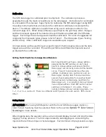
Setting the DIP switches to Assign Board Numbers
Each input board must have a unique address
assigned by the DIP switches on each input
board. A unique address will ensure that the
Data Logger will correctly read all of the boards
set up. If two or more boards have the same
address, multiple errors could occur such as:
Data Logger reading data from one board one
second, then reading data from another board
the next second, no data being read from the
Data Logger, etc.
It is important that each board
has a unique address
. Each DIP switch has four
switches on it labeled: 1, 2, 3, and 4. These
numbers follow a binary numbering system – i.e.
1 = 1, 2 = 2, 3 = 4, and 4 = 8. There is an ON and an OFF position for each switch. OFF = 0 and
ON = 1.
Getting Started
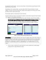
IMPORTANT: When using SDS Reporter with the Color SDS Data Logger, Options >
Color Screen Scanning must be selected. Refer to the section
Options
Color Screen
Scanning
for more details.
When logging data, the operator will use the on-board display to start and stop the data
logging / survey process. The first steps related to data logging are connecting the
inputs to the terminal strips on the data logger. Each terminal strip represents a single


