Super Systems Inc.
Page 11 of 107
Color Touch Screen Data Logger Operations Manual
analog board with 5 inputs. You can remove these terminal strips by pulling up on both
ends of the terminal strip.
Depending on the model number, you have either 20 or 40 input channels for data
logging. For each channel there will be a positive and negative connection which must
be attached to the appropriate input.
The operator defines an input type for each channel.
Once the inputs have been connected, the operator selects which inputs will be included
in the survey. This is done in two ways:
1.
When a template has been selected, the input channels setup for the template,
as defined in the Template Manager, will be the selected channels for the survey.
It is strongly suggested that you select a template prior to running a survey. If
you want to create new templates, please see the section
SDS Template
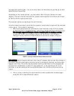
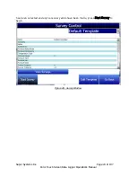
Manager. Survey Control and input selection screens are shown in Figure 7.
Figure 7 - Survey Control and Input Selection screens
IMPORTANT: Input channels defined in the Survey Template will override the settings in
the
Select Input Channel option once the survey is started. All channels are being data
logged at all times. The active inputs provide real time information on the display and
evaluation for stabilization, hottest TC and coldest TC. In the event that a TC is not
selected, it can be selected when using SDS Reporter for inclusion in the final survey
report.
2.
Once a survey is started, the input selection can be updated on the data logger
using the
Select Input Channels option.


