


Super Systems Inc.
Page 34 of 107
Color Touch Screen Data Logger Operations Manual
Logger software properly scales the raw voltage so that an accurate temperature can be
calculated. The Voltage Calibration consists of two parts: a Zero Calibration and a Span
Calibration. A Zero Calibration ensures that the raw voltage is scaled properly when the actual
voltage at a thermocouple is zero volts. A Span Calibration ensures that the raw voltage is
scaled properly when the actual voltage is 90% of the upper limit of the desired range (for
example, 72 mV when the upper limit of the range is 80 mV).
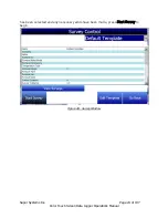
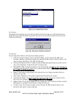
Figure 39 shows what the Voltage Calibration screen looks like.
Figure 39 - Voltage Calibration screen
The horizontal row of numbers represents each circuit board containing five inputs. The
vertical column of numbers represents each individual input. A 20-input SDS Data
Logger will feature four circuit boards depicted on this screen, while a 40-input unit will
feature eight circuit boards. Since each board has five inputs, a Voltage Calibration
usually involves five inputs on the same board at one time. A single input can be
calibrated if it is suspected that the temperature reading associated with one input is
incorrect.
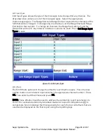
Range Value: The mV value shown in the drop-down box represents the range value for
the particular kind of thermocouple wire that you are using in the calibration. Pressing
the question mark (“?”) will bring up a window that shows the range value specific to
various kinds of thermocouple wire.
Zero or Span: Check “Zero” to perform a Zero Calibration. Check “Span” to perform a
Span Calibration.
All or Use Selected: Check “All” to calibrate all inputs. Check “Use Selected” to
calibrate a group of inputs selected by pressing the Select Inputs button and choosing
the inputs that you want to calibrate.


