


37
Internal parts
Ch
ap
te
r 2
De
sc
ript
io
n
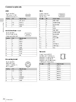
FAN4 Fan Header
This 3-pin jumper connector supplies power to the Fan
Edge Adapter Board and receives the fan speed signal
back.
FAN1- FAN3 Hot Swap Fan Headers
These 12-pin jumper connectors provide connections to
the hot swappable system fans.
DC_OU9 and DC_O10 Power Headers
The DC_OU9 4-pin power header provides dc power
supply to the Slim Power Distribution Board.
The DC_O10 4-pin power header is used for high power
add-in-card (such as graphic card that requires additional
power).
SIGNAL LED switch board
Header
This 16-pin jumper connector
provides communication between
the System Power Board to the
LED switch board through the
Front Panel Cable. Switch control,
LED driving signals and dc power
supplies are routed through to the
front panel controls and indicators.
DC_OU1 - DC_OU8 Power Out Headers
These 10-pin power out headers are connected to the
backplane board to provide power to hard disk drives.
MP1, MP2 Thermocouple Threshold Jumper Headers
Two 4-pin jumpers define the thermocouple threshold
setting of two thermocouples (1 and 2). If the temperature
feedback from the thermocouple exceeds the threshold
setting, the beeper will emit an audible alarm and the fan
failed LED on the front panel will turn on.
Pin
Signal Name
1
Fan TACH
2
+12 V
3
GND
Pin
Signal Name
Pin
Signal Name
1
2
3
4
5
6
7
8
9
10
11
12
Pin
Signal Name
1
+12 V
2
GND (Common)
3
GND (Common)
4
+5 V
Pin
Signal Name
Pin
Signal Name
1
Power Switch 1
2
Power Switch 2
3
Sys Reset Switch 1
4
Sys Reset Switch 2
5
Alarm Reset
6
Fail LED Negative (-)
7
Access LED (+)
8
Access LED (-)
9
LAN1 LED (-)
10
LAN1 LED (+)
11
LAN2 LED (-)
12
LAN2 LED (+)
13
GND
14
GND
15
+5 V
16
+5 V
Pin
Signal Name
Pin
Signal Name
1
+5 V
2
+5 V
3
GND
4
GND
5
+12 V
6
+5 V
7
GND 8
GND
9
+12 V
10
+12 V
Summary of Contents for HDXS-C200
Page 2: ...2 ...
Page 10: ...10 Table of Contents ...
Page 13: ...13 Functional description Chapter 1 Overview ...
Page 68: ...68 PuTTY terminal emulator Chapter 4 Utilities ...
Page 96: ...96 Powered off replacement parts Chapter 6 Parts Replacement ...
Page 101: ...101 Parts location Chapter 8 Spare Parts Parts location 1 2 2 2 2 2 2 2 2 2 2 2 2 ...
Page 102: ...102 Parts location Chapter 8 Spare Parts 101 102 103 104 104 104 104 104 104 104 104 104 ...
Page 104: ...104 Parts location Chapter 8 Spare Parts A B A B 301 302 303 304 305 306 306 306 306 306 ...
Page 105: ...105 ...
Page 106: ...Sony Corporation ...


