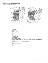


Description, device design, dimension drawing
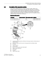
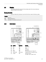
2.5 Operator controls
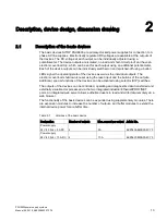
PSU8600power supply systems
26
Manual, 04.2016, A5E35883207-7-76
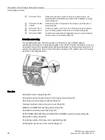
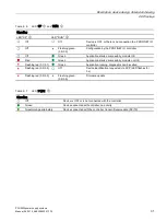
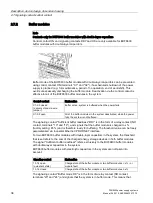
⑥
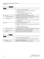
DIP switch "UI-4"
Defines the response of output 4 when an overload occurs; see
ELECTRONIC SHUTDOWN and CONSTANT CURRENT operating
⑦
,
⑧
DIP switch "STDA",
"STDB"
Defines the switch-on sequence of the outputs, see Setting the on
⑨
DIP switch "P1+2"
Connects outputs 1 and 2 or 3 and 4 of the basic device in parallel;
see Connecting outputs of the basic unit in parallel (Page 69).
⑩
DIP switch "P3+4"
⑪
DIP switch "WEN"
Activates and deactivates the integrated web server, see Activating
the web server on the module (Page 72)
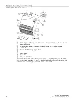
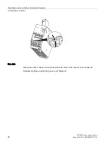
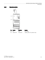
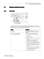
Protection and sealing
The operating elements, with the exception of the buttons, are protected against
unauthorized operation by a transparent plastic cover. When required, this plastic cover can
be sealed to prevent the operating elements being actuated by unauthorized personnel. For
sealing, the sealing wire can be routed through an opening in the plastic cover and housing,
as shown in the diagram below.
See also
Setting the output voltage (Page 53)
Setting the response threshold value of the output current (Page 54)
Switching-in and switching-out outputs (Page 55)
Overload shutdown and carrying out a reset (Page 56)
MANUAL and REMOTE operating modes (Page 59)
Prioritization when the power fails (Page 62)
ELECTRONIC SHUTDOWN and CONSTANT CURRENT operating modes (Page 64)
Setting the on delay (Page 66)
Connecting outputs of the basic unit in parallel (Page 69)
Activating the web server on the module (Page 72)
Summary of Contents for SITOP BUF8600
Page 6: ...Overview PSU8600power supply systems 6 Manual 04 2016 A5E35883207 7 76 ...
Page 12: ...Safety instructions PSU8600power supply systems 12 Manual 04 2016 A5E35883207 7 76 ...
Page 246: ...Environmental conditions PSU8600power supply systems 246 Manual 04 2016 A5E35883207 7 76 ...
Page 250: ...Environment PSU8600power supply systems 250 Manual 04 2016 A5E35883207 7 76 ...