Installation
6.6 Connecting the control contact and signaling contacts of the buffer module
PSU8600power supply systems
Manual, 04.2016, A5E35883207-7-76
115
6.6
Connecting the control contact and signaling contacts of the buffer
module
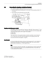
Buffer modules with double-layer capacitors have one control contact and two signaling
contacts.
●
Buffer operation can be enabled, inhibited or exited using control contact "X1" and "X2".
●
Information about the charge state of the buffer module can be obtained via signaling
contact "13" and "14".
●
Information about buffer operation can be obtained via signaling contact "23" and "24".
Control contact
The control contact is implemented as contact pair and when delivered has a wire jumper.
Instead of the wire jumper, a floating contact can be switched in the plant or system. This
means for a scheduled operational shutdown of the power supply, buffer operation is
prevented, therefore unnecessarily discharging the buffer module. Buffer operation is
immediately exited if the contact is opened during buffer operation.
Note
When closed, the contact must have a resistance < 10 Ohm.
The precise function of the control contact is described under Buffer modules (Page 38) and
in Section Activating and deactivating buffer operation (Page 80).
You can obtain more information about the assignment of the control contact under
Summary of Contents for SITOP BUF8600
Page 6: ...Overview PSU8600power supply systems 6 Manual 04 2016 A5E35883207 7 76 ...
Page 12: ...Safety instructions PSU8600power supply systems 12 Manual 04 2016 A5E35883207 7 76 ...
Page 246: ...Environmental conditions PSU8600power supply systems 246 Manual 04 2016 A5E35883207 7 76 ...
Page 250: ...Environment PSU8600power supply systems 250 Manual 04 2016 A5E35883207 7 76 ...

