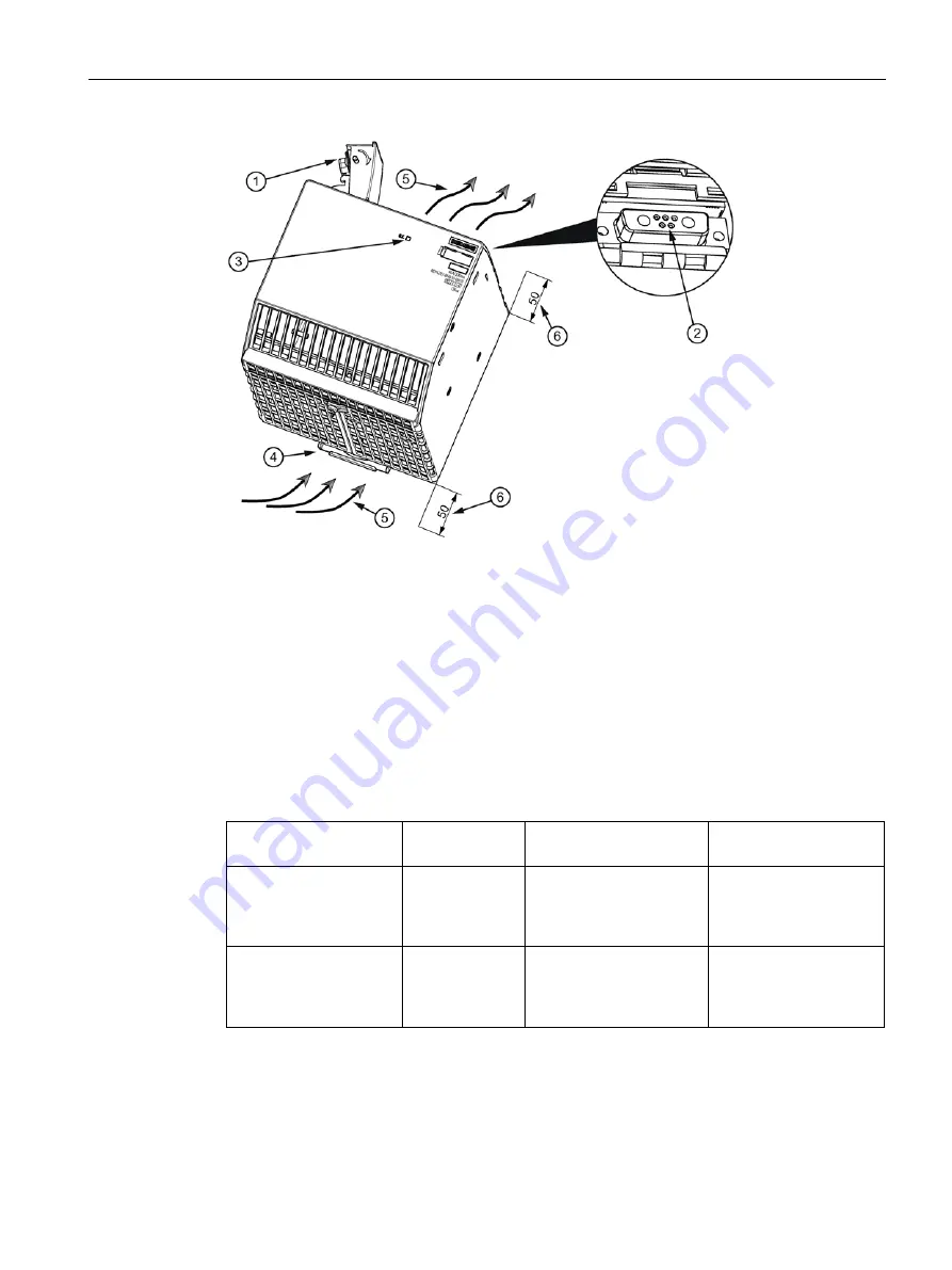
Description, device design, dimension drawing
2.3 Description of the buffer modules
PSU8600power supply systems
Manual, 04.2016, A5E35883207-7-76
17
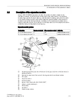
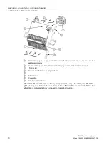
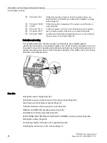
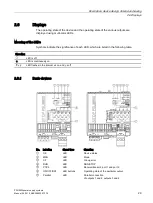
①
Connecting plug at the upper side of the device for the plug connection to the basic unit or
additional modules.
②
Socket at the upper side of the device for the plug connection to additional modules
③
"O.K." LED
④
DIN rail slider
⑤
Convection
⑥
Clearance above/below
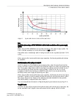
When the buffer module with electrolytic capacitors is completely charged (LED "O.K." lights
green) power failures of 100 ms or 300 ms can be buffered with a load current of 40 A. The
buffer time is correspondingly increased for lower load currents.
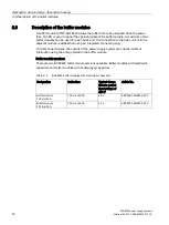
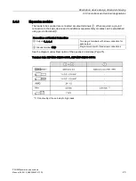
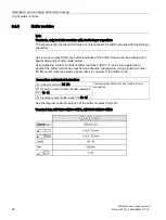
Table 2- 3
BUF8600 buffer modules with double-layer capacitors
Designation
Buffer time
Charge time for a rated
input voltage of 400 V
Article number
4 s/40 A buffer module
4 s at 40 A
typ. 5 min;
max. 8 min
(when completely dis-
charged)
6EP4293-8HB00-0XY0
10 s/40 A buffer module 10 s at 40 A
typ. 10 min;
max. 18 min
(when completely dis-
charged)
6EP4295-8HB00-0XY0
Summary of Contents for SITOP BUF8600
Page 6: ...Overview PSU8600power supply systems 6 Manual 04 2016 A5E35883207 7 76 ...
Page 12: ...Safety instructions PSU8600power supply systems 12 Manual 04 2016 A5E35883207 7 76 ...
Page 246: ...Environmental conditions PSU8600power supply systems 246 Manual 04 2016 A5E35883207 7 76 ...
Page 250: ...Environment PSU8600power supply systems 250 Manual 04 2016 A5E35883207 7 76 ...

