11/03
Setpoint Channel and Closed-Loop Control
SINAMICS G150
Operating Manual
7-7
7.2.5
Further Settings
7.2.5.1
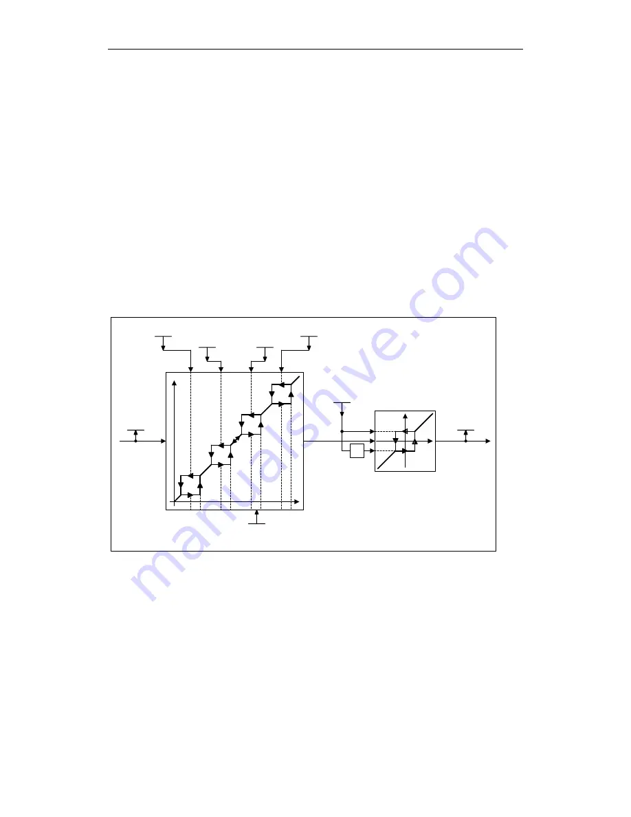
Suppression Speed and Minimum Speed
Description
Variable-speed drives can generate critical whirling speeds within the control range
of the entire drive train. This prevents steady-state operation in their proximity; in
other words, although the drive can pass through this range, it must not stop
because resonant oscillations may be excited. The skip frequency bands allow this
range to be blocked for steady-state operation. Because the points at which critical
whirling speeds occur in a drive train can vary depending on age or thermal factors,
a larger control range must be blocked. To ensure that the speed does not
constantly increase and decrease in the skip frequency band range (speeds), the
bands are assigned a hysteresis.
Signal Flow Diagram
Suppress. speed 2
p1092
Suppress. speed 3
p1093
Suppress. speed 1
p1091
Suppress. speed 4
p1094
Minimum speed
Minimum speed
p1080
-1
x
x
y
y
|x|
|y|
w
w
w
w
x
y
n_Suppr.Bandwidth
p1101
Setp_after_Lim
r1114
nSet_afterSkip
r1112
Fig. 7-4
Signal flow diagram: Suppression speeds and minimum speeds
Summary of Contents for SINAMICS G150
Page 2: ......
Page 22: ...Device Overview 11 03 SINAMICS G150 2 10 Operating Manual ...
Page 196: ...Diagnosis Faults and Alarms 11 03 SINAMICS G150 10 54 Operating Manual ...
Page 208: ...Maintenance and Servicing 11 03 SINAMICS G150 11 12 Operating Manual ...
Page 234: ......
Page 238: ...Parameterlist 11 03 SINAMICS G150 Parameterlist 4 Operating Manual ...
Page 239: ......


