


2.8
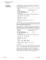
SEL-787 Relay
Instruction Manual
Date Code 20081022
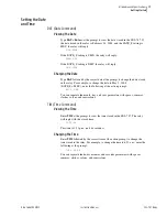
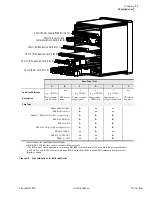
Installation
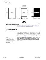
I/O Configuration
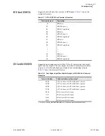
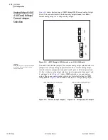
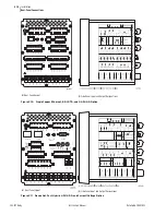
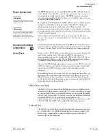
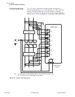
I/O Card (8 DI)
Supported in any nonbase unit slot (Slot
C, D,
or
E
), this card has eight digital
shows the terminal allocation.
I/O Card
Configuration
Procedure
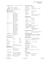
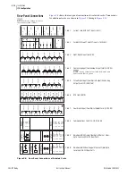
Changing card positions, or expanding on the initial number of cards requires
no card programming; the relay detects the new hardware and updates the
software accordingly (you still have to program the I/O settings using the
SET
command).
Swapping Optional I/O Boards
When an I/O board is moved from one slot to a different slot, the associated
settings for the slot the card is moved from will be lost. For example, if a
4 DI/4 DO card is installed in Slot 4 (Slot
D
), the SEL
OGIC
settings OUT401–
404 would be available. If OUT401= IN101 and 51P1T and the card is moved
to a different slot, then the OUT4xx settings will be lost. This is true for all
the digital and analog I/O cards.
Following a change in configuration, the relay is always disabled until you
accept the new relay configuration. To change the configuration, perform the
following steps:
Disconnect or de-energize all external
connections before opening this
device. Contact with hazardous
voltages and currents inside this
device can cause electrical shock
resulting in injury or death.
!
DANGER
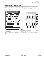
Step 1. De-energize the relay.
Step 2. Remove the eight rear-panel screws, ground screw, plug-in
connectors, and the rear panel.
Step 3. Remove the card from the relay.
Step 4. Insert the new card into the slot.
Step 5. Replace the rear panel, reinstall all screws and connectors, and
energize the unit.
Step 6. If the option card is in the proper slot, the front-panel displays
the following:
STATUS FAIL
XXX Card Failure
If you
do not
see this message and the
ENABLED
light is turned
on, the card was inserted into the wrong slot. Begin again at
.
If you
do
see this message, then proceed to
Step 7. Press the
{ESC}
pushbutton.
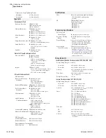
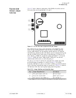
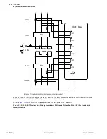
Table 2.9
Eight Digital Input (8 DI) Card Terminal Allocation
Terminal Number
Software Reference, Description
a
a
x = 3, 4, or 5 (e.g., IN401, IN402, etc., if the card was installed in Slot
D
).
01, 02
INx01, drives INx01 element
03, 04
INx02, drives INx02 element
05, 06
INx03, drives INx03 element
07, 08
INx04, drives INx04 element
09, 10
INx05, drives INx05 element
11, 12
INx06, drives INx06 element
13, 14
INx07, drives INx07 element
15, 16
INx08, drives INx08 element
Summary of Contents for SEL-787
Page 1: ...20081022 SEL 787 Transformer Protection Relay Instruction Manual PM787 01 NB ...
Page 6: ...This page intentionally left blank ...
Page 12: ...This page intentionally left blank ...
Page 18: ...This page intentionally left blank ...
Page 78: ...This page intentionally left blank ...
Page 206: ...This page intentionally left blank ...
Page 280: ...This page intentionally left blank ...
Page 334: ...This page intentionally left blank ...
Page 376: ...This page intentionally left blank ...
Page 388: ...This page intentionally left blank ...
Page 474: ...This page intentionally left blank ...
Page 508: ...This page intentionally left blank ...