
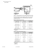

4.29
Date Code 20081022
Instruction Manual
SEL-787 Relay
Protection and Logic Functions
Basic Protection
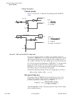
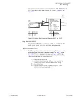
You can perform tripping directly by inclusion of the Relay Word bit REF1F
into one or more of the trip variables, TRXFMR, TR1, or TR2, as appropriate.
If you want additional security, the relay is programmed to use REF1F to
torque control an inverse-time curve for delayed tripping, as discussed below.
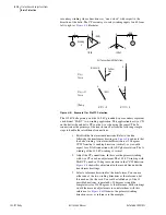
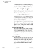
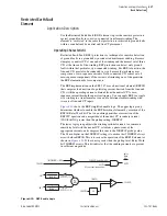
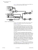
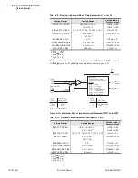
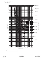
shows the output of the REF1 protection function. Timing is on an
extremely inverse-time overcurrent curve (curve U4) at the time-dial setting
(0.5) and with 50REF1P as the pickup setting.
Figure 4.12
REF Protection Output (Extremely Inverse-Time O/C)
Relay Word bit REF1F (forward fault) torque controls the timing curve, and
IN1 operates the timing function. The curve resets in one cycle if current
drops below pickup or if REF1F deasserts. When the curve times out, Relay
Word bit REF1P asserts. You can use this bit directly as an input to the
appropriate trip variables, TR
x
(where
x
= 1, 2, or XFMR), to trip the breaker
or breakers that feed the fault.
The setting REF1POL tells the relay which winding or combination of
windings it should use in calculating residual current, which acts as the
polarizing quantity for the directional element.
The setting REF1TC is a
SEL
OGIC
control equation setting that defines the
conditions under which the relay will enable REF1. A logical state of 1 for
this control equation enables the other REF1 settings and satisfies one of the
conditions the REF1 element needs to activate.
You can set the neutral current sensitivity threshold to as low as 0.05 times
nominal current (0.25 A for 5 A nominal CT current), the minimum neutral
current sensitivity of the relay. However, the minimum acceptable value of
50REF1P must meet two criteria:
1. 50REF1P must be greater than the highest unbalance expected
by load conditions.
2. 50REF1P must be greater than a minimum value determined by
the relationship of the CTR
n
values used in the REF function.
You must set the threshold setting, 50REF1P, at the greater of the two criteria
values. Determine criterion 1 for load unbalance. The second criterion relates
to the relative sensitivity of the winding CTs compared to the neutral CT. See
sample calculations
later in this section.
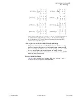
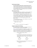
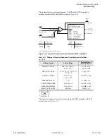
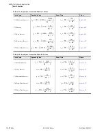
Table 4.5
Restricted Earth Fault Settings
Setting Prompt
Setting Range
Setting Name :=
Factory Default
POL QTY FROM WDG
OFF, 1, 2, 12
REF1POL := OFF
REF1 TRQ CTRL
SEL
OGIC
REF1TC := 1
REF1 CURR LEVEL
0.05–3.00 pu
50REF1P := 0.25
50REF1P*INOMN1
(RW = Relay Word bit)
|IN1|
_
+
REF1P
(RW)
REF1F
(RW)
50REF1P (pickup)
U4 Curve
TD 0.5
Reset 1 cycle
Timing
Summary of Contents for SEL-787
Page 1: ...20081022 SEL 787 Transformer Protection Relay Instruction Manual PM787 01 NB ...
Page 6: ...This page intentionally left blank ...
Page 12: ...This page intentionally left blank ...
Page 18: ...This page intentionally left blank ...
Page 78: ...This page intentionally left blank ...
Page 206: ...This page intentionally left blank ...
Page 280: ...This page intentionally left blank ...
Page 334: ...This page intentionally left blank ...
Page 376: ...This page intentionally left blank ...
Page 388: ...This page intentionally left blank ...
Page 474: ...This page intentionally left blank ...
Page 508: ...This page intentionally left blank ...