

4.27
Date Code 20081022
Instruction Manual
SEL-787 Relay
Protection and Logic Functions
Basic Protection
Restricted Earth Fault
Element
Application Description
Use the Restricted Earth Fault (REF) element to provide sensitive protection
against ground faults in your wye-connected transformer winding. The
element is “restricted” in the sense that protection is restricted to ground faults
within a zone defined by neutral and line CT placement.
Operating Characteristic
Restricted Earth Fault (REF) protection is a technique for sensitive detection
of ground faults in a grounded wye-connected transformer winding. Because
it employs a neutral CT at one end of the winding and the normal set of three
CTs at the line end of the winding, REF protection can detect only ground
faults within that particular wye-connected winding. For REF to function, the
line-end CTs must also be connected in wye, because the technique uses
comparison of zero-sequence currents. Delta-connected CTs cancel out all
zero-sequence components of the currents, eliminating one of the quantities
the REF element needs for comparison.
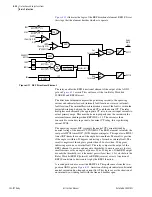
The REF implementation in the SEL-787 uses a directional element (REF1F)
that compares the direction of a polarizing current, derived from the line-end
CTs, with the operating current, obtained from the neutral CT. A zero-
sequence current threshold supervises tripping. You can apply REF to a single
wye winding in a transformer or to an entire autotransformer winding with
two sets of line-end CT inputs.
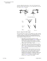
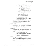
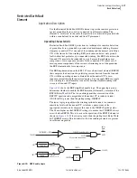
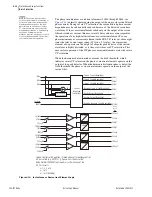
shows the REF simplified enable logic. The upper logic group
determines whether to enable the REF directional element by assertion of the
REF1E Relay Word bit. The two enabling quantities are assertion of the
REF1TC equation and a magnitude of the neutral CT secondary current
(IN1/I
NOM
N1) greater than the pickup setting, 50REF1P.
The lower logic group adjusts the winding residual currents to a common
sensitivity level with the neutral CT, calculates a phasor sum of the
appropriate currents, and compares this sum to the 50REF1P pickup value.
The 0.8 multiplier on the 50REF1P setting is to ensure that 50GREF1 always
asserts before REF1E. This is to secure the operation of the REF1F element as
shown in
. If the sum is greater than the pickup level, Relay Word
bit 50GREF1 asserts. This bit indicates that the winding currents are present
in sufficient magnitude.
Figure 4.10
REF Enable Logic
0.8
Σ
REF1E
|IGWPU|
1
INOMW1
1
INOMW2
IGW1
IGW2
Relay
Word
Bits
50REF1P
50GREF1
|IN1|/INOMN1 = IN1PU
50REF1P
REF1TC
(SEL
OGIC
control equation)
50NREF1 (Relay Word Bit)
REF1POL = 1, 12
REF1POL = 2, 12
Summary of Contents for SEL-787
Page 1: ...20081022 SEL 787 Transformer Protection Relay Instruction Manual PM787 01 NB ...
Page 6: ...This page intentionally left blank ...
Page 12: ...This page intentionally left blank ...
Page 18: ...This page intentionally left blank ...
Page 78: ...This page intentionally left blank ...
Page 206: ...This page intentionally left blank ...
Page 280: ...This page intentionally left blank ...
Page 334: ...This page intentionally left blank ...
Page 376: ...This page intentionally left blank ...
Page 388: ...This page intentionally left blank ...
Page 474: ...This page intentionally left blank ...
Page 508: ...This page intentionally left blank ...