

4.28
SEL-787 Relay
Instruction Manual
Date Code 20081022
Protection and Logic Functions
Basic Protection
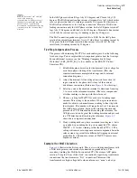
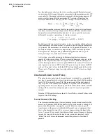
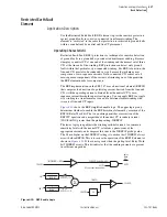
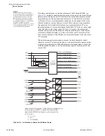
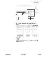
illustrates the logic of the REF directional element, REF1F. It is at
this stage that the element decides whether to operate.
Figure 4.11
REF Directional Element
The relay enables the REF1 directional element if the output of the AND2
gate in
asserts. This will occur if the two Relay Word bits
50GREF1 and REF1E assert.
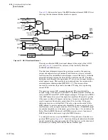
The directional element compares the polarizing current to the operating
current and indicates forward (internal) fault location or reverse (external)
fault location. The internal/forward indication occurs if the fault is within the
protected winding, between the line-end CTs and the neutral CT. The relay
multiplies each current by the appropriate CT ratio to convert input currents to
actual primary amps. This must be done to properly sum the currents in the
autotransformer windings when REF1POL = 12. The current is then
converted to secondary in per unit of nominal CT rating, this is polarizing
current, IPOL.
The operating current, IOP, is simply the neutral CT current divided by
nominal rating of the neutral CT, INOMN1. The REF1 element calculates the
real part of IPOL times IOP* (IOP complex conjugate). This equates to |IPOL|
times |IOP| times the cosine of the angle between them. The result is positive
if the angle is within ±90 degrees, indicating a forward or internal fault. The
result is negative if the angle is greater than +90 or less than -90 degrees,
indicating a reverse or external fault. The relay compares the output of the
REF1 element to positive and negative thresholds, to ensure security for very
small currents or for an angle very near +90 or -90 degrees. If the REF1 output
exceeds the threshold test, it then must persist for at least 1.5 cycles before the
Relay Word bit REF1F (forward) or REF1R (reverse) asserts. Assertion of
REF1F constitutes a decision to trip by the REF1 function.
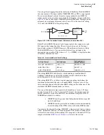
A second path can also assert the REF1F bit. This path comes from the two-
position AND1 gate in
. Assertion of this gate indicates substantial
neutral current and no line-end current flow. This logic covers the situation of
an internal wye-winding fault with the line-end breaker open.
1.5
cyc
0
1.5
cyc
0
Σ
52A1
52A2
REF1POL = 1, 12
REF1POL = 2, 12
REF1POL = 1, 12
REF1POL = 2, 12
|IGWPU|
(from Fig. 4.10)
0.02
IN1PU
(from Fig 4.10)
(K*50REF1P)
OR1
OR2
AND1
AND2
50GREF1
REF1E
Pos.
Threshold
Neg.
Threshold
REF1F
REF1R
RE(IPOL•lOP*)
1
CTRN1*INOMW
1
INOMN1
IGW1
IGW2
CTR1
CTR2
Relay
Word
Bits
IPOL
lOP
IN1
Summary of Contents for SEL-787
Page 1: ...20081022 SEL 787 Transformer Protection Relay Instruction Manual PM787 01 NB ...
Page 6: ...This page intentionally left blank ...
Page 12: ...This page intentionally left blank ...
Page 18: ...This page intentionally left blank ...
Page 78: ...This page intentionally left blank ...
Page 206: ...This page intentionally left blank ...
Page 280: ...This page intentionally left blank ...
Page 334: ...This page intentionally left blank ...
Page 376: ...This page intentionally left blank ...
Page 388: ...This page intentionally left blank ...
Page 474: ...This page intentionally left blank ...
Page 508: ...This page intentionally left blank ...