


4.71
Date Code 20081022
Instruction Manual
SEL-787 Relay
Protection and Logic Functions
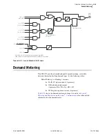
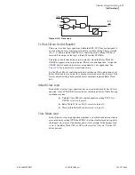
Trip/Close Logic
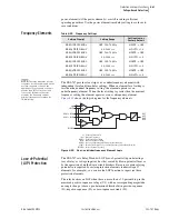
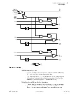
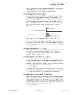
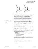
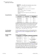
Figure 4.45
Close Logic
CL Close SEL
OGIC
Control Equation
There are two close logic equations within the SEL-787. They are designed to
operate when
SEL
OGIC
control equation close variable setting CL
m
is asserted
(
m
= 1, 2) and to unlatch when
SEL
OGIC
control equation setting ULCL
m
is
asserted. The output of the logic is Relay Word bits CLOSE
m
.
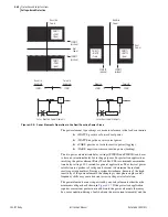
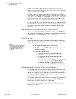
The relay controls the closing output contact(s) when the Relay Word bit
CLOSE
m
appears in an output contact SEL
OGIC
control equation. Assign the
CLOSE bits to desired output relays as required by your application. See
for typical close circuit connection.
Set the CL
m
SEL
OGIC
control equations to include an OR-combination of all
Relay Word bits that you want to cause the associated close bits to assert. The
factory default setting already includes all commonly required Relay Word
bits.
Unlatch Close Logic
Each of the two close logic equations has an associated unlatch close
SEL
OGIC
equation. Once a CLOSE bit is asserted it is sealed-in until all of the following
conditions are true:
➤
Unlatch Close SEL
OGIC
control equation setting ULCL1 (or
ULCL2) asserts to logical 1.
➤
Relay Word 52A1 (or 52A2) asserts to logical 1.
➤
Close failure Relay Word bit asserts to logical 1.
Close Failure Logic
Each of the two close logic equations includes a close failure detection with an
associated delay setting (CFD1 and CFD2). Set the close failure delay equal to
the longest close time of the breaker plus a safety margin. If the breaker fails
to close, the Relay Word CF1 (or CF2) will assert for 1/4 cycle. Use the CF
bits as desired.
CFD1
0
CL1
ULCL1
CLOSE1
CF1
Close Failure Timer
SEL
OGIC
Equations
52A1
Relay
Word
Bits
Summary of Contents for SEL-787
Page 1: ...20081022 SEL 787 Transformer Protection Relay Instruction Manual PM787 01 NB ...
Page 6: ...This page intentionally left blank ...
Page 12: ...This page intentionally left blank ...
Page 18: ...This page intentionally left blank ...
Page 78: ...This page intentionally left blank ...
Page 206: ...This page intentionally left blank ...
Page 280: ...This page intentionally left blank ...
Page 334: ...This page intentionally left blank ...
Page 376: ...This page intentionally left blank ...
Page 388: ...This page intentionally left blank ...
Page 474: ...This page intentionally left blank ...
Page 508: ...This page intentionally left blank ...