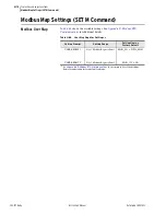
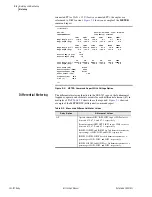


5.14
SEL-787 Relay
Instruction Manual
Date Code 20081022
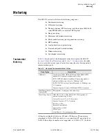
Metering and Monitoring
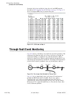
Through-Fault Event Monitoring
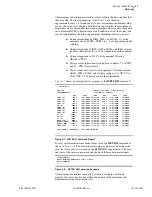
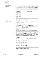
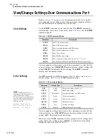
There are only four settings to set the though-fault event monitor, all under the
Through Fault category in Global Settings (SET G Command) (see
). Enable the through fault element by setting the SEL
OGIC
equation
ETHRFLT for the conditions that you what the element to run. Use Setting
THFLTD to select the winding that you want the element to use when
calculating the through-fault current. Switch S1 in
selects OFF or
one of windings 1 or 2. Set the through-fault alarm pickup (THFLTPU) to the
desired value, and enter the transformer percentage impedance at the XFMRZ
setting.
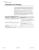
NOTE:
When you change the
ETHRFLT setting, the relay also clears
the data and records, i.e., it has the
same effect as the
TFE C
or
TFE R
command.
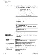
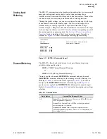
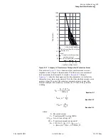
On the basis that mechanical stress takes effect only at high current values, the
through-fault element runs only if the selected phase current is greater than
4.75 times full load current. Allowing a hysteresis of 0.25 of full load, the
through-fault element resets when the current falls below 4.5 times the full
load current.
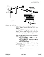
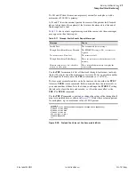
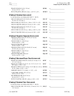
shows a functional diagram of the through-fault element for the
A-phase of Winding 1 (THFLTD = 1), the B-phase and C-phase elements
have identical diagrams. When SEL
OGIC
equation ETHRFLT asserts and the
A-phase current exceeds 4.75 times the transformer full-load current, Enable
asserts and the 1-minute Timer starts. When Enable asserts, the following
occurs:
➤
The thermal element advances the A-phase fault counter by
1 count.
➤
The thermal element advances the total fault counter by
1 count.
➤
The thermal element records the time when the fault starts
(rising edge of Enable).
➤
The process to determine the maximum through-fault current
for the fault duration starts.
➤
The integration process starts, whereby the element sums the
values (
) calculated each processing interval (1/4
of a power system cycle).
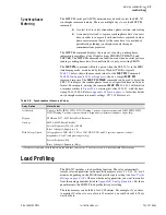
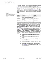
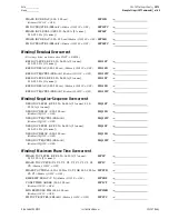
Table 5.10
Through-Fault Element Settings
Setting
Description
Range
THFLTD
Identifies the winding whose phase
currents will be used in the thermal element
OFF, 1, 2
ETHRFLT
Enable Through-Fault Monitor (SEL
OGIC
Equation)
SEL
OGIC
Equation
THFLTPU
Through-Fault Alarm Pickup
50.0–900.0 %
XFMRZ
Percentage Transformer Impedance
2.0–40.0 %
Summary of Contents for SEL-787
Page 1: ...20081022 SEL 787 Transformer Protection Relay Instruction Manual PM787 01 NB ...
Page 6: ...This page intentionally left blank ...
Page 12: ...This page intentionally left blank ...
Page 18: ...This page intentionally left blank ...
Page 78: ...This page intentionally left blank ...
Page 206: ...This page intentionally left blank ...
Page 280: ...This page intentionally left blank ...
Page 334: ...This page intentionally left blank ...
Page 376: ...This page intentionally left blank ...
Page 388: ...This page intentionally left blank ...
Page 474: ...This page intentionally left blank ...
Page 508: ...This page intentionally left blank ...