background image

E-022-4-E

8

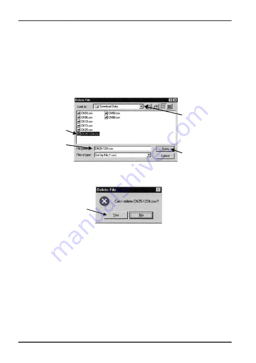
3.10.3 Delete File

You can delete any file that is no longer needed.

 Click on "File (F)" at the top-level menu of the screen, select "Database (F)", select "Delete File (X) 

Ctrl+X," and click on agin.

 Select the disk and folder that contains the file you want to remove from the drop-down list.

 Select the file you want to remove by clicking. Acknowledge "File name" and click on "Open" button.

  In  response  to  the  clicking,  the  file  you  selected  opens  and  a  message  box  as  shown  in  Fig.  24 

appears.  Click  on  "Yes"  button  if  you  want  to  delete,  or  "No"  if  you  do  not  want.  Clicking  on  "Yes" 

deletes that file.

Click on the icon 

of file you want to 

delete.

Click here and select 

the disk and folder 

which contains the file 

you want to delete.

Click "Open" button.

Fig.23

Fig.24

Filename is shown.

Click on this button 

deletes the file. 

Summary of Contents for EL 2310-05E Series

Page 1: ...olis Flowmeters ULTRAmass MK Mass Flex STmass MK VRmass Transmitters CT9401 ST9801 EV9201 MT9411 MT9603 MT9431 For the installation of application software LinkTop and the interface driver refer to In...

Page 2: ...tatus input 2 3 6 7 Status output 22 3 6 8 H L alarm 24 3 6 9 Error Output Select Error select 26 3 6 0 Output Level in an Error Error indicator 28 3 6 Burst Mode Setup HART output 29 3 6 2 Bore size...

Page 3: ...No Rsponse 63 3 13 If Connecting the Flowmeter Fails 63 3 4 Input Errors 64 3 Error Messages 6 3 6 Parameters 66 4 PRODUCT CODE EXPLANATION 69 5 GENERAL SPECIFICATIONS 70 CONVENTIONS Shown in this ma...

Page 4: ...f measurement or from a terminal in a remote location Using a Windows PC at hand you can monitor multiple windows on its screen 1 The EL2310 operates on the application software LinkTop furnished 2 Th...

Page 5: ...driver Interface Adapter Fig 1 2 BEFORE YOU BEGIN 2 1 Inspection Upon Receipt Be sure you have the following items Remove the products from the EL2310 carton and make sure you have all the components...

Page 6: ...t set up with associated equipment and devices are shown in Fig 2 NOTE In Fig 2 the customer is to supply the PC that meets the following requirements PC AT compatible DOS V machine Operating system i...

Page 7: ...approx Cable length from connector 1000 approx 50 Probe 60 E 022 4 E Fig 3 2 3 PC Interface Adapter Comprised of components as shown in Fig 3 it converts the flowmeter transmitter signal Bell 202 int...

Page 8: ...g 4 shows how the LinkTop window looks like Fig 4 Menu PC to Flowmeter Communications Status Title Bar Message Box Field The state of communications is indicated at bottom left of the screen by During...

Page 9: ...r left of the PC screen and click LinkTop for Coriolis 3 J from Program Click Port setting I Ctrl I in File F at the top level menu of screen Set up the port Select the option labeled COM USB and clic...

Page 10: ...cted is automatically identified and the transmitter name appears in the title bar A message indicating ongoing communication appears at lower left of the screen with IDLE RX WAIT shown alternately Up...

Page 11: ...menu on the screen as shown in Fig 12 select Disconnect U Shift F3 and click on again At the message box as shown in Fig 13 click on OK This brings the connection between the flowmeter and LinkTop to...

Page 12: ...level menu of the screen select Exit E and click on again A message box as shown in Fig 15 appears If you are sure to exit the LinkTop click on OK button Clicking on OK button will cause the applicat...

Page 13: ...t the top level menu of the screen and click on View fl dev avers again A message box for measuring process variables appears as shown in Fig 17 In ST9801 there is no Volume Flow menu In EV9201 neithe...

Page 14: ...ariable V at top level menu on the screen select Totalizer cntl and click on again A message box for measuring the total flow appears as shown in Fig 19 Fig 19 Total flow comes in F Total R Total and...

Page 15: ...comparing against Menu Review a list of setup parameters If Dia Service T message box is shown on the screen you cannot set up parameters transmitter information etc Close that message box Epsom befo...

Page 16: ...the flowmeter output also changes with the changes in settings made For safety s sake therefore in applications where the flowmeter output controls a valve s or other devices it is necessary that the...

Page 17: ...t up density unit density damping slug flow identification and density correction In slug flow identification any flow in which the obtained density measurement exceeds preselected Slug low limit or S...

Page 18: ...previous settings are replaced with the new settings just entered in response to clicking on OK a message box as shown in Fig 27 appears Clicking on OK button at this point completes the setup Fig 26...

Page 19: ...n all the fields required click on OK button A message box as shown in Fig 29 then appears Clicking on OK at this window changes the previous settings to the new settings just entered However the flow...

Page 20: ...he fields required click on OK button A message box as shown in Fig 32 then appears Clicking on OK at this window changes the previous settings to the new settings just entered However the flowmeter o...

Page 21: ...terminal in a remote location Default setting is No Function To disable the status input function select No Function You can select the status input from two types of input a form contact input or b f...

Page 22: ...Click on Cancel button to hide the setup message box To abort the setup process click on Cancel button in the course of steps through 3 6 7 Status Output Click on Setup S at top level menu of the scre...

Page 23: ...on If No Function is your option the status output remains OFF By the way status output logic is selectable in Status output mode Default is OFF that is to say OFF active is selected If you want to us...

Page 24: ...Fig 43 appears H L alarm related items are set up here H L alarm is a function to turn the status output OFF when the item set at H L alarm vars reaches High alarm point or Low alarm point where Statu...

Page 25: ...other devices it is necessary that the control loop be switched to manual control to ensure that the control loop is unaffected by the flowmeter output When the previous settings are replaced with th...

Page 26: ...Setup S at top level menu of the screen select Error select from Conf output drop down list and click on again A message box as shown in Fig 46 appears Items to be assigned to the status output are s...

Page 27: ...age box as shown in Fig 48 appears Clicking on OK button at this point completes the setup After clicking on OK button the message box for filling in fields of items appears again Click on Cancel butt...

Page 28: ...r items refer to 3 15 Error Messages After filling in all the fields required click on OK button A message box as shown in Fig 51 then appears Clicking on OK at this window changes the previous settin...

Page 29: ...click on again A message box as shown in Fig 3 appears Burst mode is set up at this window The burst mode is a function in which the process data are continuously transferred from the flowmeter transm...

Page 30: ...hen the previous settings are replaced with the new settings just entered in response to clicking on OK a message box as shown in Fig 6 appears Clicking on OK button at this point completes the setup...

Page 31: ...ings are replaced with the new settings just entered in response to clicking on OK a message box as shown in Fig 60 appears Clicking on OK button at this point completes the setup 60 Following clickin...

Page 32: ...ing on OK a message box as shown in Fig 63 appears Clicking on OK button at this point completes the setup Fig 63 CAUTION Flowmeter calibration factor has already been set up before shipment from the...

Page 33: ...icking on OK button the message box for filling in fields of individual items appears again Click on Cancel button to hide the message box for filling in fields of items To abort the setup process cli...

Page 34: ...r information are set up at this window Fig 67 You are to set up individual items For items with an arrow mark at right click on the arrow mark at right and select one desired from the drop down list...

Page 35: ...es it is necessary that the control loop be switched to manual control to ensure that the control loop is unaffected by the flowmeter output When the previous settings are replaced with the new settin...

Page 36: ...emains disabled Close the message box Epsom before you work Also at Diag Service T message box multiple message boxes cannot be shown simultaneously except for Loop test 3 7 1 Transmitter Diagnostics...

Page 37: ...on OK button returns the screen to the Test Status message box Results of self test appear in the window below the Test Status message box as shown in Fig 75 No problems in particular A message Good a...

Page 38: ...begins the transmitter LCD display shows a repeated performance of all elements lighting up and going off for five times You can inspect the LCD for any sign of damage by this test When the LCD displa...

Page 39: ...op level menu of the screen select Fix Analog from the Loop test drop down list and click on again Click here Fig 79 Fig 80 A message box like the one shown in Fig 80 appears Select the simulated outp...

Page 40: ...Fig 83 In response to clicking on Stop button a message box like the one shown in Fig 83 appears Click on OK button Clicking on OK button returns the screen to the Fix Analog 1 message box Click on C...

Page 41: ...ssage box like the one shown in Fig 84 appears Select the simulated output and click on Start button To provide an output other than 0kHz select Other key in the pulse frequency you want for the outpu...

Page 42: ...t is used here irrespective of the status of the process in applications where the flowmeter output controls valves or other devices it is necessary for the sake of safety that the control loop be cha...

Page 43: ...licking on OK button returns the screen to the Fix Status output message box Click on Cancel button to hide the Fix Status output message box 3 7 7 Loop Test of Status Input Status input The status of...

Page 44: ...rs Select key operation ON or OFF and click on OK button Fig 93 A message box like the one in Fig 94 appears If it is desired to change key operation status click on OK To cancel click on Cancel Click...

Page 45: ...n drop down list and click on again Click here Fig 96 A message box as shown in Fig 97 appears Stop the flow completely first and then click on OK A message box like the one in Fig 98 appears If you w...

Page 46: ...o hide the Auto Zero message box CAUTION It is necessary that the zero point adjustment be conducted while the process fluid is stable and at the operating temperature The process fluid inside the sen...

Page 47: ...e shown in Fig 0 appears To start the density calibration fill the sensor flow tube with density calibration fluid key in the density value of calibration fluid and click on OK button A message box as...

Page 48: ...OK button the screen returns to Density cal message box Click on Cancel button to hide the Density cal message box Fig 104 CAUTION Density calibration has already been made in the factory before shipm...

Page 49: ...hat the control loop is unaffected by the flowmeter output Click on Diag Service T at top level menu of the screen select Trim Analog 1 and click on again A message box as shown in Fig 106 appears If...

Page 50: ...or selecting the 4mA or 20mA trim Make the 4mA trim here followed by the 20mA trim Enter the ammeter reading of the current output and click on OK button As the reading is transferred the transmitter...

Page 51: ...like the one shown in Fig appears Select either the 4mA trim or the 20mA trim Firstly the 20mA trim is described here followed by the 20mA trim Key in the reading of the test instrument and click on O...

Page 52: ...rameters at the Review window 3 8 1 Transmitter Status Xmtr status Transmitter status is indicated at this window Click on Review R at the top level menu of the screen select Xmtr status and click on...

Page 53: ...ck on Cancel 3 8 3 Flow Calibration Factor Charize sensor Flowrate and density factors of the flowmeter transmitter are indicated at this window Click on Review R at the top level menu of the screen s...

Page 54: ...s To hide the message box for reviewing transmitter variables click on Cancel In the EV9201 Density menu item is not included 3 8 5 View Outputs Individual outputs of the transmitter are indicated at...

Page 55: ...one On the screen shown below 3 8 2 Transmitter Info is indicated as active The window with a check mark is currently acive Clicking on the name of the window you want to activate turns that window a...

Page 56: ...mer 3 10 1 Open File You can read the data saved in a file by the procedure below Click on File F at the top level menu of the screen select Database F select Open File O Ctrl 0 and click on again Fig...

Page 57: ...ick on again Select from the drop down list the disk and folder into which you want to save the data Type in the filename of the file you want to save and click on Save button Saving a file is now com...

Page 58: ...le you want to remove by clicking Acknowledge File name and click on Open button In response to the clicking the file you selected opens and a message box as shown in Fig 124 appears Click on Yes butt...

Page 59: ...ubject to downloading Click on the file you want to download Make sure of Folder name N and click on Open D button On seeing a message box like the one shown in Fig 126 click on OK button if you want...

Page 60: ...on OK button brings out a message box as shown in Fig 27 The bar graph at the center of message box tells you the progress of downloading Fig 127 When downloading is completed a message box like the...

Page 61: ...the top level menu of the screen select Print P Cntl P and click on again On seeing a window like the one shown in Fig 129 click on OK button Through a series of these steps of operation you can obtai...

Page 62: ...0 Added damp 0 0 sec Analog output 2 Assign Temperature URV 100 000 LRV 0 000 Lowcut 0 0 Added damp 0 0 sec Pulse output Assign Mass Flow Freq factor 1000 00 Hz Rate factor 180 0000 kg min Lowcut 0 6...

Page 63: ...above checks make connections all over again according to the procedure outlined in 3 2 Starting the LinkTop and Connection 3 13 If Connecting the Flowmeter Fails When the flowmeter is connected accor...

Page 64: ...ter as data is sent to the flowmeter transmitter With all menu items selected and OK button clicked when an error is found in any of these settings a warning error box appears as shown in Fig 132 Clic...

Page 65: ...ture out of 220 220 range Err 24 Density Outside Limits Density out of 0 5g mL range Err 25 P O Sig Alarm AD input out of 10 95 range Transmitter Failure Err 31 EEPROM Error EEPROM checksum error Seek...

Page 66: ...ecs set 5 Vol flow unit Volume flow unit select Specs set 6 Flow direction Flow direction select Specs set 7 Flow damp Mass Flow mass damping Specs set 8 Flow cutoff Flow mass cutoff Specs set 9 Dens...

Page 67: ...select Specs set 34 High alarm point High alarm setpoint Specs set 35 Low alarm point Low alarm setpoint Specs set Error Select 36 Saturated alarm Error output ON OFF select Specs set 37 Sensor failu...

Page 68: ...set 65 Zero factor Zero factor Specs set Transmitter Information 66 Tag Tag No Specs set 67 Descriptor Descriptor Specs set 68 Message Message Specs set 69 Date Date of manufacture Factory set 70 Dev...

Page 69: ...ce 0 Less interface application software only 1 Interface provided Media application software 1 CD ROM 9 Other than above Reserved code 0 Always 0 NOTES 2 Application software LinkTop for EL2300 with...

Page 70: ...eter transmitter output Reads sets up and saves parameters Stored in FD HD or other external Trims analog outputs Checks analog output loop Confirms diagnostic messages Requires installation of a dedi...

Page 71: ...E 022 4 E 71...

Page 72: ...E 022 4 E 20 8 03 Revised 2009 0 Released E 022 4 E All specifications are subject to change for improvement...

Reviews: