


E-022-4-E
9
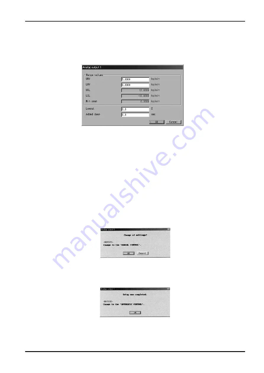
Fig.28
Fig.29
Fig.30
3.6.3 Analog output 1
①
Click on "Setup (S)" at the top-level menu of the screen, select "Analog Output 1" from " Config output"
drop-down menu, and click on again.
②
A message box like the one shown in Fig. 28 appears. Analog output is set up at this window.
③
You are to set up individual items. Acceptable ranges of USL (sensor's upper limit), LSL (sensor's
lower limit), Min. Span are shown at URV (setting at 20mA) and LRV (setting at 4mA) as a guide to
your entering setpoints.
The low cutoff function is "OFF" when your "Lowcut" option is "0.0%"
.
Default is "0.0%"
. When items
other than flowrate (mass and volume) are assigned, do not fail to set to "0.0%"
.
If "Bi direction" is
chosen, the low cutoff functions both in the forward and reverse directions.
④
After filling in all the fields required, click on "OK" button. A message box as shown in Fig. 29 then
appears.
Clicking on "OK" at this window changes the previous settings to the new settings just entered.
However, the flowmeter output also changes with the changes in settings made. For safety's
sake, therefore, in applications where the flowmeter output controls a valve (s) or other devices, it
is necessary that the control loop be switched to manual control to ensure that the control loop is
unaffected by the flowmeter output.
⑤
When the previous settings are replaced with the new settings just entered in response to clicking on
"OK"
,
a message box as shown in Fig. 30 appears. Clicking on "OK" button at this point completes the
setup.
⑥
Clicking on "OK" brings the screen to return to the message box for filling in fields of items.
Click on "Cancel" button to hide the message box for filling in fields of items.
To abort the setup process, click on "Cancel" button in the course of steps
②
through
④
.
Summary of Contents for EL 2310-05E Series
Page 71: ...E 022 4 E 71...


