Component Serviceability, Locations, and Designations
70
Sun Server X4-4 Service Manual • October 2015
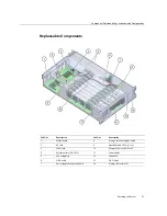
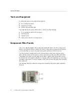
Call Out
Description
Call Out
Description
0
Fan Module, FM 0
3
Fan Module, FM 3
1
Fan Module, FM 1
4
Fan Module, FM 4
2
Fan Module, FM 2
5
Fan Module, FM 5
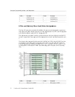
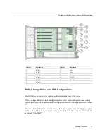
CPUs and Memory Riser Card Slots Designations
The four CPU sockets are located in the middle of the server and are designated consecutively
from right to left (from the front of the server). The rightmost socket is CPU-0 and is designated
as P0, and the leftmost socket is CPU-3, designated as P3.
The eight memory riser (MR) card slots are located between the fan module slots and the CPU
sockets. Consecutively from right to left, the rightmost slot is slot 0, and the leftmost slot is slot
7.
The slots are also designated by their association with the four CPU sockets (P0-P3). Two slots
are assigned to each CPU socket. For example, slots 0 and 1 are paired with CPU socket, P0,
and are designated as P0/MR0 and P0/MR1. Slots 2 and 3 are paired with CPU socket, P1 and
are designated as P1/MR0 and P1/MR1. This numbering pattern continues for the remaining
slots.
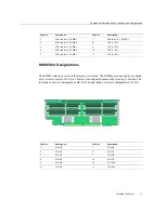
Call Out
Description
Call Out
Description
0
MR card slot 0, P0/MR0
6
MR card slot 6, P3/MR0
Summary of Contents for Sun Server X4-4
Page 1: ...Part No E38221 05 October 2015 Sun Server X4 4 Service Manual ...
Page 2: ......
Page 10: ...10 Sun Server X4 4 Service Manual October 2015 ...
Page 14: ...14 Sun Server X4 4 Service Manual October 2015 ...
Page 16: ...16 Sun Server X4 4 Service Manual October 2015 ...
Page 64: ...64 Sun Server X4 4 Service Manual October 2015 ...
Page 88: ...88 Sun Server X4 4 Service Manual October 2015 ...
Page 280: ...280 Sun Server X4 4 Service Manual October 2015 ...
Page 284: ...284 Sun Server X4 4 Service Manual October 2015 ...
Page 292: ...292 Sun Server X4 4 Service Manual October 2015 ...

