4-57
4-2 Function Mode
4
Functions
External Analog Input Disconnection Detection
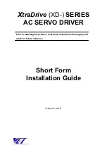
• Outputs a signal if an error is detected in the external analog inputs (FV, FI).
• The disconnection detection signal is output if the frequency reference of the external analog input
remains below the starting frequency for 500 ms.
• The signal stops 500 ms after the frequency reference has exceeded the starting frequency.
• Helps detect disconnection when a frequency reference is issued from the external analog inputs
(FV, FI) with the frequency reference selection set to the terminal (A001 = 01).
• Enabled only when the external analog inputs (FV, FI) are selected.
Example 1: Disabled in multi-step speed operation even when the frequency reference is set to
the external analog input (A001 = 01).
Example 2: Disabled even when the FV/FI selection is set to the FV/VR selection (A005 = 02) or
FI/VR selection (A005 = 03) since the frequency reference is set on the Digital Op-
erator (volume) with the AT terminal turned on.
Data
Symbol
Function name
Status
Description
05
AL
Alarm output
ON
The Inverter is in trip status.
OFF
The Inverter is normal.
Available input terminals
P1-PC, P2-PC, MA-MC (or MB-MC)
Required settings
C021, C026
Data
Symbol
Function name
Status
Description
06
Dc
Disconnection detection
ON
The Inverter is in trip status.
OFF
The Inverter is normal.
Available input terminals
P1-PC, P2-PC, MA-MC (or MB-MC)
Required settings
C021, C022, C026, A001, A005
Starting
frequency
0Hz
External analog
input disconnection
detection (DC)
OFF
ON
500 ms
500 ms
External analog input frequency
reference (FV, FI)
Summary of Contents for SYSDRIVE 3G3MX-A2002
Page 1: ...Cat No I559 E1 01 USER S MANUAL SYSDRIVE MXSERIES Multi function Compact Inverter...
Page 17: ...Chapter 1 Overview 1 1 Functions 1 1 1 2 Appearance and Names of Parts 1 3...
Page 24: ......
Page 25: ...Chapter 2 Design 2 1 Installation 2 1 2 2 Removing and Mounting Each Part 2 5 2 3 Wiring 2 10...
Page 90: ......
Page 91: ...Chapter 4 Functions 4 1 Monitor Mode 4 1 4 2 Function Mode 4 5...
Page 180: ......
Page 181: ...Chapter 5 Maintenance Operations 5 1 Special Display List 5 1 5 2 Troubleshooting 5 5...
Page 188: ......
Page 189: ...Chapter 6 Inspection and Maintenance 6 1 Inspection and Maintenance 6 1 6 2 Storage 6 7...
Page 212: ...7 15 7 5 Options 7 Specifications 3G3AX RBU41 95 75 2 5 208 218 5 145 35 100 5...
Page 230: ......
Page 231: ...Appendix Appendix 1 Parameter List App 1 Appendix 2 Product Life Curve App 17...
Page 249: ...INDEX...
Page 252: ......