


www.omega.com
e-mail: [email protected]
www.omega.com/software
User’s Guide
MICROMEGA
®
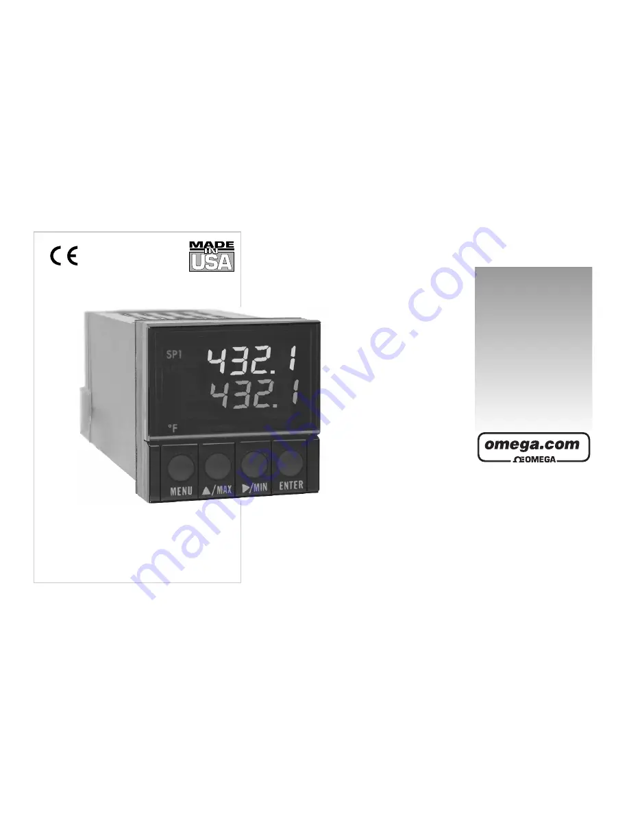
CN77000 Series Controller
®
®
Shop on line at
Summary of Contents for MICROMEGA CN77000 series
Page 4: ...NOTES ...
Page 19: ...SETUP part 2 11 Dip Switch Settings ...
Page 31: ...Figure 3 2 Flowchart for Input Type OPERATION CONFIGURATION MODE part 3 23 ...
Page 36: ...Figure 3 3 Flowchart for Reading Configuration part 3 OPERATION CONFIGURATION MODE 28 ...
Page 45: ...Figure 3 5 Flowchart for Loop Break OPERATION CONFIGURATION MODE part 3 37 ...
Page 49: ...OPERATION CONFIGURATION MODE part 3 41 Figure 3 6 Flowchart for Output 1 ...
Page 59: ...OPERATION CONFIGURATION MODE part 3 51 Figure 3 7 Flowchart for Output 2 ...
Page 65: ...OPERATION CONFIGURATION MODE part 3 57 Figure 3 8 Flowchart for Ramp Soak ...


