


Hardware Installation
2-21
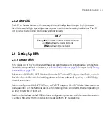
2.8.2 Rear LED
The LED on the rear (bottom) of the access point is optionally viewed using a single (customer
installed) extended light pipe, adjusted as required to suit above the ceiling installations. The LED
light pipe has the following color display and functionality:
2.9 Setting Up MUs
2.9.1 Legacy MUs
For a discussion of how to initially test the access point to ensure it can interoperate with the MUs
intended for its operational environment, see
Basic Configuration on page 3-4
and specifically
Testing
Connectivity on page 3-20
.
Refer to the
LA-5030 & LA-5033 Wireless Networker PC Card and PCI Adapter Users Guide,
available
from the Motorola Web site, for installing drivers and client software if operating in an 802.11a/g
network environment.
Refer to the
Spectrum24 LA-4121 PC Card, LA-4123 PCI Adapter & LA-4137 Wireless Networker User
Guide,
available from the Motorola Web site, for installing drivers and client software if operating in
an 802.11b network environment.
Use the default values for the ESSID and other configuration parameters until the network connection
is verified. MUs attach to the network and interact with the AP transparently.
LED 7
Blinking
Red
(160 msec) indicates a failure condition.
Solid
Red
defines the diagnostic mode.
White
defines normal operation.
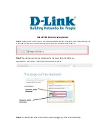
Summary of Contents for AP-7131N-FGR
Page 1: ...AP 7131N FGR Access Point Product Reference Guide ...
Page 3: ...AP 7131N FGR Access Point Product Reference Guide 72E 126727 01 Revision A September 2009 ...
Page 4: ......
Page 55: ...Hardware Installation 2 11 ...
Page 68: ...AP 7131N FGR Access Point Product Reference Guide 2 24 ...
Page 90: ...AP 7131N FGR Access Point Product Reference Guide 3 22 ...
Page 148: ...AP 7131N FGR Access Point Product Reference Guide 4 58 ...
Page 300: ...AP 7131N FGR Access Point Product Reference Guide 6 72 ...
Page 338: ...AP 7131N FGR Access Point Product Reference Guide 7 38 ...
Page 635: ...Configuring Mesh Networking 9 23 5 Define a channel of operation for the 802 11a n radio ...
Page 648: ...AP 7131N FGR Access Point Product Reference Guide 9 36 ...
Page 672: ...AP 7131N FGR Access Point Product Reference Guide 10 24 line con 0 line vty 0 24 end ...
Page 692: ...AP 7131N FGR Access Point Product Reference Guide B 14 ...
Page 698: ...AP 7131N FGR Access Point Product Reference Guide B 20 ...
Page 702: ...AP 7131N FGR Access Point Product Reference Guide C 4 ...
Page 707: ......