


AP-7131N-FGR Access Point Product Reference Guide
2-12
1.
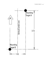
Xerox copy the template (on the previous page) to a blank piece of paper. Do not reduce or
enlarge the scale of the template.
2.
Tape the template to the wall mounting surface.
• If the installation requires the antenna be positioned vertically, the centerline reference
(of the template) needs to be positioned vertically. The cabling shall exit the access point
in a vertical direction.
• If the installation requires the antenna be positioned horizontally, the vertical centerline
(of the template) needs to be positioned horizontally. The cabling shall exit the access
point in a horizontal direction.
3.
At mounting targets A and B, mark the mounting surface through the template at the target
center.
4.
Discard the mounting template.
5.
At each point, drill a hole in the wall, insert an anchor, screw into the anchor the wall
mounting screw and stop when there is 1mm between the screw head and the wall.
If pre-drilling a hole, the recommended hole size is 2.8mm (0.11in.) if the screws are going
directly into the wall and 6mm (0.23in.) if wall anchors are being used.
6.
If required, install and attach a security cable to the access point’s lock port.
7.
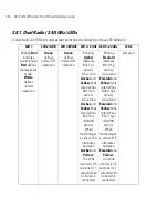
Attach the antennas to their correct connectors.
For more information on available antennas, see
Antenna Options on page 2-4
.
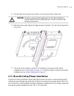
8.
Place the large center opening of each of the mount slots over the screw heads.
9.
Slide the access point down along the mounting surface to hang the mount slots on the
screw heads.
CAUTION
If printing the mounting template (on the previous page) from an
electronic PDF, dimensionally confirm the template by measuring each
value for accuracy.
CAUTION
Ensure you are placing the antennas on the correct connectors
(depending on your dual-radio model and frequency used) to ensure
the successful operation of the access point.
NOTE
It is recommended the access point be mounted with the RJ45 cable
connector oriented upwards or downwards to ensure proper operation.
!
!
Summary of Contents for AP-7131N-FGR
Page 1: ...AP 7131N FGR Access Point Product Reference Guide ...
Page 3: ...AP 7131N FGR Access Point Product Reference Guide 72E 126727 01 Revision A September 2009 ...
Page 4: ......
Page 55: ...Hardware Installation 2 11 ...
Page 68: ...AP 7131N FGR Access Point Product Reference Guide 2 24 ...
Page 90: ...AP 7131N FGR Access Point Product Reference Guide 3 22 ...
Page 148: ...AP 7131N FGR Access Point Product Reference Guide 4 58 ...
Page 300: ...AP 7131N FGR Access Point Product Reference Guide 6 72 ...
Page 338: ...AP 7131N FGR Access Point Product Reference Guide 7 38 ...
Page 635: ...Configuring Mesh Networking 9 23 5 Define a channel of operation for the 802 11a n radio ...
Page 648: ...AP 7131N FGR Access Point Product Reference Guide 9 36 ...
Page 672: ...AP 7131N FGR Access Point Product Reference Guide 10 24 line con 0 line vty 0 24 end ...
Page 692: ...AP 7131N FGR Access Point Product Reference Guide B 14 ...
Page 698: ...AP 7131N FGR Access Point Product Reference Guide B 20 ...
Page 702: ...AP 7131N FGR Access Point Product Reference Guide C 4 ...
Page 707: ......